INTELLECTUM VIRTUS
INTELLECTUM VIRTUS
INTELLECTUM VIRTUS
INTELLECTUM VIRTUS
INTELLECTUM VIRTUS
ELECTRICAL ENGINEERING
ELECTRICAL ENGINEERING
ELECTRICAL ENGINEERING
ELECTRICAL ENGINEERING
ELECTRICAL ENGINEERING
PASSIVE COMPONENT REGISTER
PASSIVE COMPONENT REGISTER
PASSIVE COMPONENT REGISTER
PASSIVE COMPONENT REGISTER
PASSIVE COMPONENT REGISTER
Capacitor, Inductor, Resistor & Memristor
Capacitor, Inductor, Resistor & Memristor
Capacitor, Inductor, Resistor & Memristor
Capacitor, Inductor, Resistor & Memristor
Capacitor, Inductor, Resistor & Memristor
Capacitor, Inductor, Resistor & Memristor
Capacitor, Inductor, Resistor & Memristor
Capacitor, Inductor, Resistor & Memristor
Capacitor, Inductor, Resistor & Memristor
| CAPACITORS · INDUCTORS · TRANSFORMERS MEMRISTORS · RESISTORS · IDENTITY |
| CAPACITORS · INDUCTORS · TRANSFORMERS MEMRISTORS · RESISTORS · IDENTITY |
| CAPACITORS · INDUCTORS · TRANSFORMERS MEMRISTORS · RESISTORS · IDENTITY |
| CAPACITORS · INDUCTORS · TRANSFORMERS MEMRISTORS · RESISTORS · IDENTITY |
| CAPACITORS · INDUCTORS · TRANSFORMERS MEMRISTORS · RESISTORS · IDENTITY |
| Capacitors, an overview |
| Capacitors, an overview |
| Capacitors, an overview |
| Capacitors, an overview |
| Capacitors, an overview |
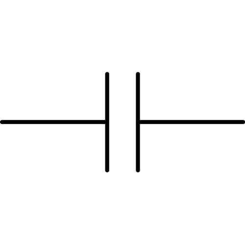
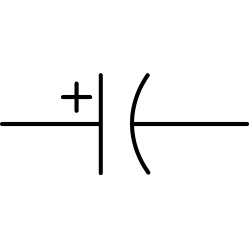
| Includes: Ceramic, Electrolytic, Elemental, Film, Light Emitting, Super, and Variable. Definition: The Capacitor, C, as 1 of 4 passive components, has 2 fundamental variables of Charge and Voltage. Measured in units of Capacitance (C / V, or Farad), C = dq / dV. Capacitors store a wide range of electric charges and consists of a minimum of two conducting surfaces (plates), separated by an insulator (dielectric) and depending on type, may require a vacuum, gas or electrolytic solution. History: The first capacitor, known as the Kleistian jar, then the Leyden jar, condensers or permittors, to capacitors, a two-terminal electrical component to store electricity and at least two electrical conductors (called “plates”) separated by an insulating layer (called the “dielectric”) allowing them to retain a charge. They are used in all forms of electronics from amplifiers, filters, tuned circuits or as part of a power supply system to smooth rectified currents, whereas larger capacitors are used for energy storage, lighting, electric motors, power factor correction in AC power distribution systems. Non-Polarised Capacitors have dielectrics made of Ceramic, Film, Paper, Air, Glass, Silicon or a Vacuum. Polarised Capacitors (electrolytic) are made of Aluminium, Tantalum, Niobium, whilst Super Capacitors are made as a Double Layer, Pseudo or Hybrid of both. Components: Dielectric is an insulating material between two conducting plates of a capacitor which enables electrical charge to be stored. Dielectric examples include porcelain, mica, glass, plastic, metals oxides, dry air, distilled water and a vacuum. The official term, dielectric, was suggested to Michael Faraday by William Whewell in 1848. Electrolyte is the chemical solution used in cells and some capacitors to produce an electrically conductive storage medium. Solid crystalline salts disassociate into paired charged particles when dissolved. In forming a solution, the salt dissociates into charged particles, of which Michael Faraday had given the name “ion”. Used for this purpose in 1884 by Chemist, Svante Arrhenius |
| Includes: Ceramic, Electrolytic, Elemental, Film, Light Emitting, Super, and Variable. Definition: The Capacitor, C, as 1 of 4 passive components, has 2 fundamental variables of Charge and Voltage. Measured in units of Capacitance (C / V, or Farad), C = dq / dV. Capacitors store a wide range of electric charges and consists of a minimum of two conducting surfaces (plates), separated by an insulator (dielectric) and depending on type, may require a vacuum, gas or electrolytic solution. History: The first capacitor, known as the Kleistian jar, then the Leyden jar, condensers or permittors, to capacitors, a two-terminal electrical component to store electricity and at least two electrical conductors (called “plates”) separated by an insulating layer (called the “dielectric”) allowing them to retain a charge. They are used in all forms of electronics from amplifiers, filters, tuned circuits or as part of a power supply system to smooth rectified currents, whereas larger capacitors are used for energy storage, lighting, electric motors, power factor correction in AC power distribution systems. Non-Polarised Capacitors have dielectrics made of Ceramic, Film, Paper, Air, Glass, Silicon or a Vacuum. Polarised Capacitors (electrolytic) are made of Aluminium, Tantalum, Niobium, whilst Super Capacitors are made as a Double Layer, Pseudo or Hybrid of both. Components: Dielectric is an insulating material between two conducting plates of a capacitor which enables electrical charge to be stored. Dielectric examples include porcelain, mica, glass, plastic, metals oxides, dry air, distilled water and a vacuum. The official term, dielectric, was suggested to Michael Faraday by William Whewell in 1848. Electrolyte is the chemical solution used in cells and some capacitors to produce an electrically conductive storage medium. Solid crystalline salts disassociate into paired charged particles when dissolved. In forming a solution, the salt dissociates into charged particles, of which Michael Faraday had given the name “ion”. Used for this purpose in 1884 by Chemist, Svante Arrhenius |
| Includes: Ceramic, Electrolytic, Elemental, Film, Light Emitting, Super, and Variable. Definition: The Capacitor, C, as 1 of 4 passive components, has 2 fundamental variables of Charge and Voltage. Measured in units of Capacitance (C / V, or Farad), C = dq / dV. Capacitors store a wide range of electric charges and consists of a minimum of two conducting surfaces (plates), separated by an insulator (dielectric) and depending on type, may require a vacuum, gas or electrolytic solution. History: The first capacitor, known as the Kleistian jar, then the Leyden jar, condensers or permittors, to capacitors, a two-terminal electrical component to store electricity and at least two electrical conductors (called “plates”) separated by an insulating layer (called the “dielectric”) allowing them to retain a charge. They are used in all forms of electronics from amplifiers, filters, tuned circuits or as part of a power supply system to smooth rectified currents, whereas larger capacitors are used for energy storage, lighting, electric motors, power factor correction in AC power distribution systems. Non-Polarised Capacitors have dielectrics made of Ceramic, Film, Paper, Air, Glass, Silicon or a Vacuum. Polarised Capacitors (electrolytic) are made of Aluminium, Tantalum, Niobium, whilst Super Capacitors are made as a Double Layer, Pseudo or Hybrid of both. Components: Dielectric is an insulating material between two conducting plates of a capacitor which enables electrical charge to be stored. Dielectric examples include porcelain, mica, glass, plastic, metals oxides, dry air, distilled water and a vacuum. The official term, dielectric, was suggested to Michael Faraday by William Whewell in 1848. Electrolyte is the chemical solution used in cells and some capacitors to produce an electrically conductive storage medium. Solid crystalline salts disassociate into paired charged particles when dissolved. In forming a solution, the salt dissociates into charged particles, of which Michael Faraday had given the name “ion”. Used for this purpose in 1884 by Chemist, Svante Arrhenius |
| Includes: Ceramic, Electrolytic, Elemental, Film, Light Emitting, Super, and Variable. Definition: The Capacitor, C, as 1 of 4 passive components, has 2 fundamental variables of Charge and Voltage. Measured in units of Capacitance (C / V, or Farad), C = dq / dV. Capacitors store a wide range of electric charges and consists of a minimum of two conducting surfaces (plates), separated by an insulator (dielectric) and depending on type, may require a vacuum, gas or electrolytic solution. History: The first capacitor, known as the Kleistian jar, then the Leyden jar, condensers or permittors, to capacitors, a two-terminal electrical component to store electricity and at least two electrical conductors (called “plates”) separated by an insulating layer (called the “dielectric”) allowing them to retain a charge. They are used in all forms of electronics from amplifiers, filters, tuned circuits or as part of a power supply system to smooth rectified currents, whereas larger capacitors are used for energy storage, lighting, electric motors, power factor correction in AC power distribution systems. Non-Polarised Capacitors have dielectrics made of Ceramic, Film, Paper, Air, Glass, Silicon or a Vacuum. Polarised Capacitors (electrolytic) are made of Aluminium, Tantalum, Niobium, whilst Super Capacitors are made as a Double Layer, Pseudo or Hybrid of both. Components: Dielectric is an insulating material between two conducting plates of a capacitor which enables electrical charge to be stored. Dielectric examples include porcelain, mica, glass, plastic, metals oxides, dry air, distilled water and a vacuum. The official term, dielectric, was suggested to Michael Faraday by William Whewell in 1848. Electrolyte is the chemical solution used in cells and some capacitors to produce an electrically conductive storage medium. Solid crystalline salts disassociate into paired charged particles when dissolved. In forming a solution, the salt dissociates into charged particles, of which Michael Faraday had given the name “ion”. Used for this purpose in 1884 by Chemist, Svante Arrhenius |
| Includes: Ceramic, Electrolytic, Elemental, Film, Light Emitting, Super, and Variable. Definition: The Capacitor, C, as 1 of 4 passive components, has 2 fundamental variables of Charge and Voltage. Measured in units of Capacitance (C / V, or Farad), C = dq / dV. Capacitors store a wide range of electric charges and consists of a minimum of two conducting surfaces (plates), separated by an insulator (dielectric) and depending on type, may require a vacuum, gas or electrolytic solution. History: The first capacitor, known as the Kleistian jar, then the Leyden jar, condensers or permittors, to capacitors, a two-terminal electrical component to store electricity and at least two electrical conductors (called “plates”) separated by an insulating layer (called the “dielectric”) allowing them to retain a charge. They are used in all forms of electronics from amplifiers, filters, tuned circuits or as part of a power supply system to smooth rectified currents, whereas larger capacitors are used for energy storage, lighting, electric motors, power factor correction in AC power distribution systems. Non-Polarised Capacitors have dielectrics made of Ceramic, Film, Paper, Air, Glass, Silicon or a Vacuum. Polarised Capacitors (electrolytic) are made of Aluminium, Tantalum, Niobium, whilst Super Capacitors are made as a Double Layer, Pseudo or Hybrid of both. Components: Dielectric is an insulating material between two conducting plates of a capacitor which enables electrical charge to be stored. Dielectric examples include porcelain, mica, glass, plastic, metals oxides, dry air, distilled water and a vacuum. The official term, dielectric, was suggested to Michael Faraday by William Whewell in 1848. Electrolyte is the chemical solution used in cells and some capacitors to produce an electrically conductive storage medium. Solid crystalline salts disassociate into paired charged particles when dissolved. In forming a solution, the salt dissociates into charged particles, of which Michael Faraday had given the name “ion”. Used for this purpose in 1884 by Chemist, Svante Arrhenius |
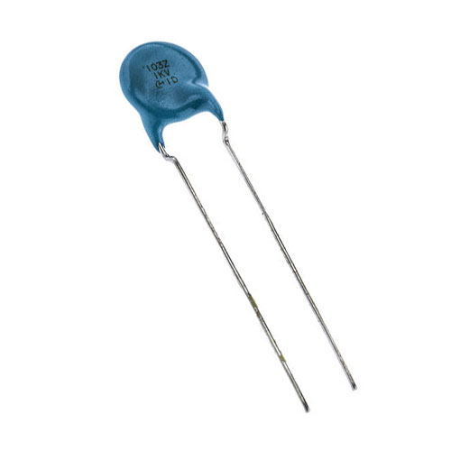
| Invented in 1745 by Ewald Georg von Kleist. |
| Invented in 1745 by Ewald Georg von Kleist. |
| Invented in 1745 by Ewald Georg von Kleist. |
| Invented in 1745 by Ewald Georg von Kleist. |
| Invented in 1745 by Ewald Georg von Kleist. |
 |
|
|
|
|
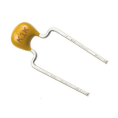
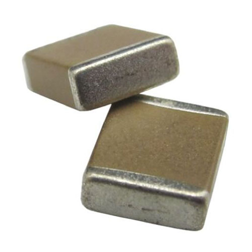
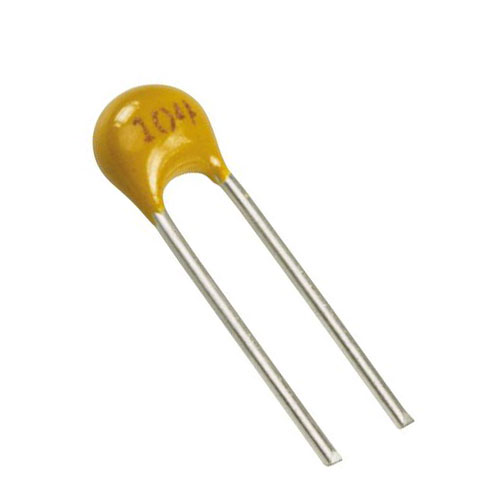
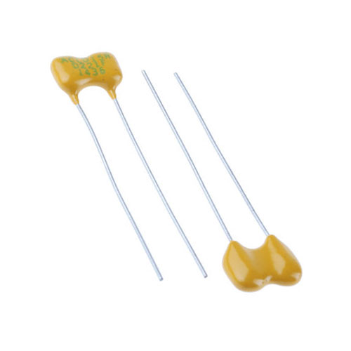
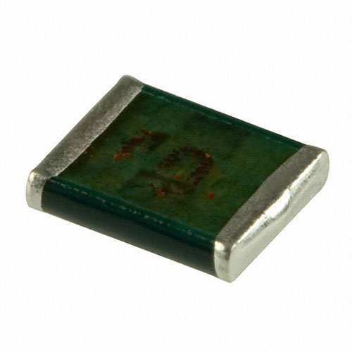
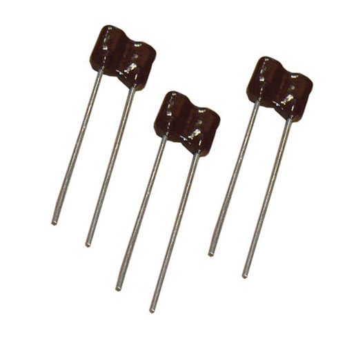
| Definition: Ceramic capacitors are made from two or more alternating layers of ceramic and metal in which the ceramic material acts as the dielectric and the metal acts as the electrodes. The ceramic material is a mixture of finely ground granules of paraelectric or ferroelectric materials, modified by mixed oxides that are necessary to achieve the capacitor’s desired characteristics and are divided into two stability classes. Class 1 has high stability with low losses and compensates for temperature within resonant circuits. Class 2 has a high volumetric efficiency for buffering, bypass and coupling applications. The construction of ceramic multilayer capacitors with mostly alternating layers results in single capacitors connected in parallel. This configuration increases capacitance and decreases all losses and parasitic inductances. Ceramic capacitors are suited for high frequencies and high current pulse loads and as the thickness of the ceramic dielectric layer can be easily controlled, the desired application voltages are available up to the 30 kV range. Special applications from RFI/EMI suppression to connection to supply mains and three-terminal capacitors for bypassing and decoupling, feed-through capacitors for noise suppression by low-pass filtration and ceramic power capacitors for transmitters. |
| Definition: Ceramic capacitors are made from two or more alternating layers of ceramic and metal in which the ceramic material acts as the dielectric and the metal acts as the electrodes. The ceramic material is a mixture of finely ground granules of paraelectric or ferroelectric materials, modified by mixed oxides that are necessary to achieve the capacitor’s desired characteristics and are divided into two stability classes. Class 1 has high stability with low losses and compensates for temperature within resonant circuits. Class 2 has a high volumetric efficiency for buffering, bypass and coupling applications. The construction of ceramic multilayer capacitors with mostly alternating layers results in single capacitors connected in parallel. This configuration increases capacitance and decreases all losses and parasitic inductances. Ceramic capacitors are suited for high frequencies and high current pulse loads and as the thickness of the ceramic dielectric layer can be easily controlled, the desired application voltages are available up to the 30 kV range. Special applications from RFI/EMI suppression to connection to supply mains and three-terminal capacitors for bypassing and decoupling, feed-through capacitors for noise suppression by low-pass filtration and ceramic power capacitors for transmitters. |
| Definition: Ceramic capacitors are made from two or more alternating layers of ceramic and metal in which the ceramic material acts as the dielectric and the metal acts as the electrodes. The ceramic material is a mixture of finely ground granules of paraelectric or ferroelectric materials, modified by mixed oxides that are necessary to achieve the capacitor’s desired characteristics and are divided into two stability classes. Class 1 has high stability with low losses and compensates for temperature within resonant circuits. Class 2 has a high volumetric efficiency for buffering, bypass and coupling applications. The construction of ceramic multilayer capacitors with mostly alternating layers results in single capacitors connected in parallel. This configuration increases capacitance and decreases all losses and parasitic inductances. Ceramic capacitors are suited for high frequencies and high current pulse loads and as the thickness of the ceramic dielectric layer can be easily controlled, the desired application voltages are available up to the 30 kV range. Special applications from RFI/EMI suppression to connection to supply mains and three-terminal capacitors for bypassing and decoupling, feed-through capacitors for noise suppression by low-pass filtration and ceramic power capacitors for transmitters. |
| Definition: Ceramic capacitors are made from two or more alternating layers of ceramic and metal in which the ceramic material acts as the dielectric and the metal acts as the electrodes. The ceramic material is a mixture of finely ground granules of paraelectric or ferroelectric materials, modified by mixed oxides that are necessary to achieve the capacitor’s desired characteristics and are divided into two stability classes. Class 1 has high stability with low losses and compensates for temperature within resonant circuits. Class 2 has a high volumetric efficiency for buffering, bypass and coupling applications. The construction of ceramic multilayer capacitors with mostly alternating layers results in single capacitors connected in parallel. This configuration increases capacitance and decreases all losses and parasitic inductances. Ceramic capacitors are suited for high frequencies and high current pulse loads and as the thickness of the ceramic dielectric layer can be easily controlled, the desired application voltages are available up to the 30 kV range. Special applications from RFI/EMI suppression to connection to supply mains and three-terminal capacitors for bypassing and decoupling, feed-through capacitors for noise suppression by low-pass filtration and ceramic power capacitors for transmitters. |
| Definition: Ceramic capacitors are made from two or more alternating layers of ceramic and metal in which the ceramic material acts as the dielectric and the metal acts as the electrodes. The ceramic material is a mixture of finely ground granules of paraelectric or ferroelectric materials, modified by mixed oxides that are necessary to achieve the capacitor’s desired characteristics and are divided into two stability classes. Class 1 has high stability with low losses and compensates for temperature within resonant circuits. Class 2 has a high volumetric efficiency for buffering, bypass and coupling applications. The construction of ceramic multilayer capacitors with mostly alternating layers results in single capacitors connected in parallel. This configuration increases capacitance and decreases all losses and parasitic inductances. Ceramic capacitors are suited for high frequencies and high current pulse loads and as the thickness of the ceramic dielectric layer can be easily controlled, the desired application voltages are available up to the 30 kV range. Special applications from RFI/EMI suppression to connection to supply mains and three-terminal capacitors for bypassing and decoupling, feed-through capacitors for noise suppression by low-pass filtration and ceramic power capacitors for transmitters. |
 |
 |
 |
 |
|
|
|
|
|
|
|
|
|
|
|
|
|
|
|
|
| Invented in 1900 by Luigi Lombardi. |
| Invented in 1900 by Luigi Lombardi. |
| Invented in 1900 by Luigi Lombardi. |
| Invented in 1900 by Luigi Lombardi. |
| Invented in 1900 by Luigi Lombardi. |
| Capacitor, Electrolytic |
| Capacitor, Electrolytic |
| Capacitor, Electrolytic |
| Capacitor, Electrolytic |
| Capacitor, Electrolytic |
 |
|
|
|
|
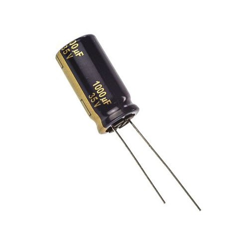
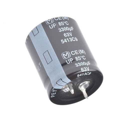
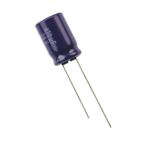
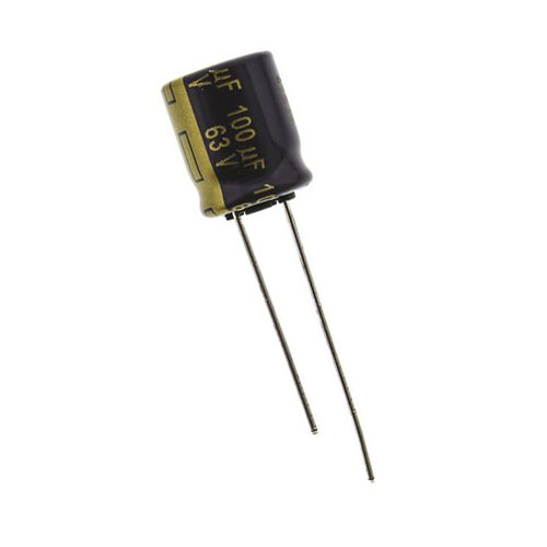
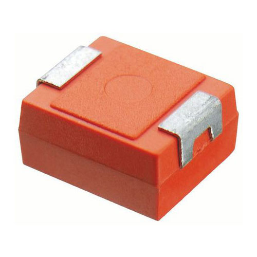
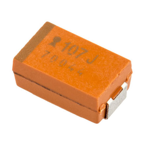
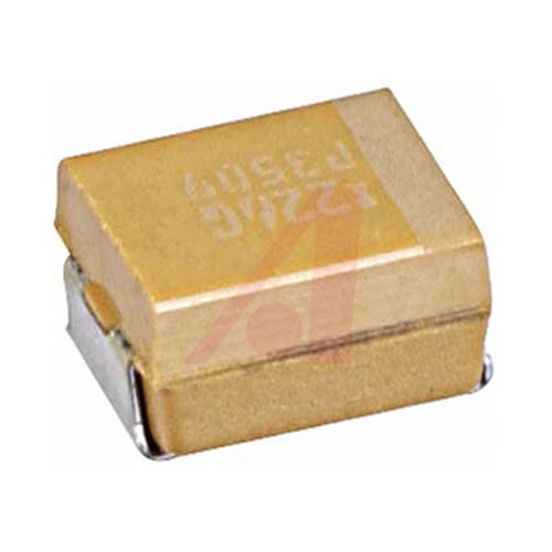
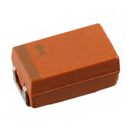
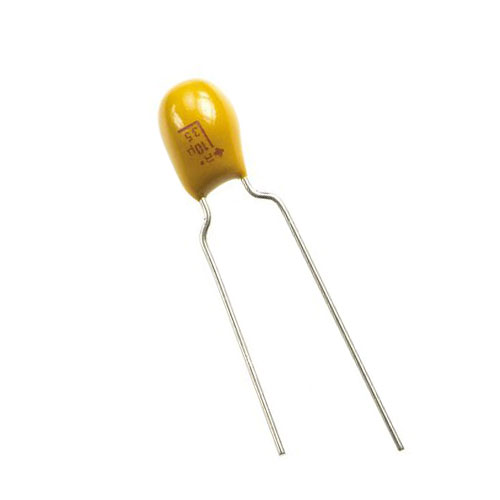
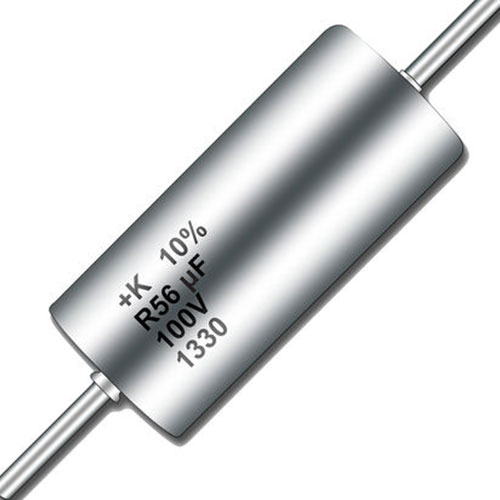
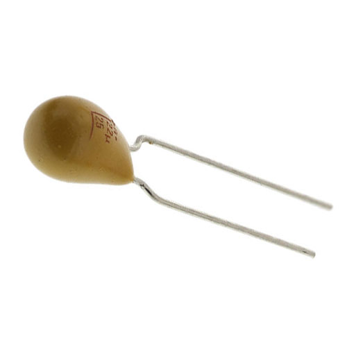
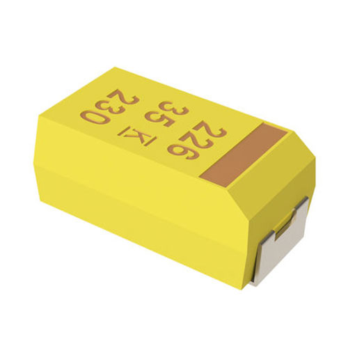
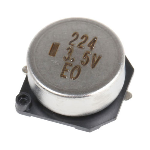
| Definition: Electrolytic capacitors have a metallic anode covered with an oxidized layer as a dielectric, the second electrode may be non-solid or solid electrolyte resulting in polarised, electrolytic capacitors. Three different dielectrics are used: aluminium oxide, tantalum pentoxide and niobium pentoxide. The anodes have a rough surface to maximise the surface area and maintain a high permittivity of the oxide layer. Electrical conductivity is determined by the electrolyte material and composition as the choice of electrolytes are wet with conductivity of 10 mS/cm or solid manganese oxide has a conductivity of 100 mS/cm, offering high quality and stability. |
| Definition: Electrolytic capacitors have a metallic anode covered with an oxidized layer as a dielectric, the second electrode may be non-solid or solid electrolyte resulting in polarised, electrolytic capacitors. Three different dielectrics are used: aluminium oxide, tantalum pentoxide and niobium pentoxide. The anodes have a rough surface to maximise the surface area and maintain a high permittivity of the oxide layer. Electrical conductivity is determined by the electrolyte material and composition as the choice of electrolytes are wet with conductivity of 10 mS/cm or solid manganese oxide has a conductivity of 100 mS/cm, offering high quality and stability. |
| Definition: Electrolytic capacitors have a metallic anode covered with an oxidized layer as a dielectric, the second electrode may be non-solid or solid electrolyte resulting in polarised, electrolytic capacitors. Three different dielectrics are used: aluminium oxide, tantalum pentoxide and niobium pentoxide. The anodes have a rough surface to maximise the surface area and maintain a high permittivity of the oxide layer. Electrical conductivity is determined by the electrolyte material and composition as the choice of electrolytes are wet with conductivity of 10 mS/cm or solid manganese oxide has a conductivity of 100 mS/cm, offering high quality and stability. |
| Definition: Electrolytic capacitors have a metallic anode covered with an oxidized layer as a dielectric, the second electrode may be non-solid or solid electrolyte resulting in polarised, electrolytic capacitors. Three different dielectrics are used: aluminium oxide, tantalum pentoxide and niobium pentoxide. The anodes have a rough surface to maximise the surface area and maintain a high permittivity of the oxide layer. Electrical conductivity is determined by the electrolyte material and composition as the choice of electrolytes are wet with conductivity of 10 mS/cm or solid manganese oxide has a conductivity of 100 mS/cm, offering high quality and stability. |
| Definition: Electrolytic capacitors have a metallic anode covered with an oxidized layer as a dielectric, the second electrode may be non-solid or solid electrolyte resulting in polarised, electrolytic capacitors. Three different dielectrics are used: aluminium oxide, tantalum pentoxide and niobium pentoxide. The anodes have a rough surface to maximise the surface area and maintain a high permittivity of the oxide layer. Electrical conductivity is determined by the electrolyte material and composition as the choice of electrolytes are wet with conductivity of 10 mS/cm or solid manganese oxide has a conductivity of 100 mS/cm, offering high quality and stability. |
| Electrolytic Aluminium |
 |
 |
 |
 |
| Electrolytic Aluminium |
|
|
|
|
| Electrolytic Aluminium |
|
|
|
|
| Electrolytic Aluminium |
|
|
|
|
| Electrolytic Aluminium |
|
|
|
|
| Electrolytic Niobium |
 |
 |
 |
 |
| Electrolytic Niobium |
|
|
|
|
| Electrolytic Niobium |
|
|
|
|
| Electrolytic Niobium |
|
|
|
|
| Electrolytic Niobium |
|
|
|
|
| Electrolytic Tantalum |
 |
 |
 |
 |
| Electrolytic Tantalum |
|
|
|
|
| Electrolytic Tantalum |
|
|
|
|
| Electrolytic Tantalum |
|
|
|
|
| Electrolytic Tantalum |
|
|
|
|
| Invented in 1931 by Julius Edgar Lilienfeld. |
| Invented in 1931 by Julius Edgar Lilienfeld. |
| Invented in 1931 by Julius Edgar Lilienfeld. |
| Invented in 1931 by Julius Edgar Lilienfeld. |
| Invented in 1931 by Julius Edgar Lilienfeld. |
| Capacitor, Elemental |
| Capacitor, Elemental |
| Capacitor, Elemental |
| Capacitor, Elemental |
| Capacitor, Elemental |
 |
|
|
|
|
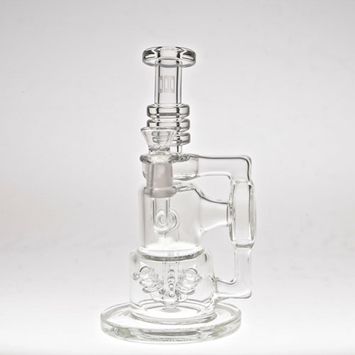
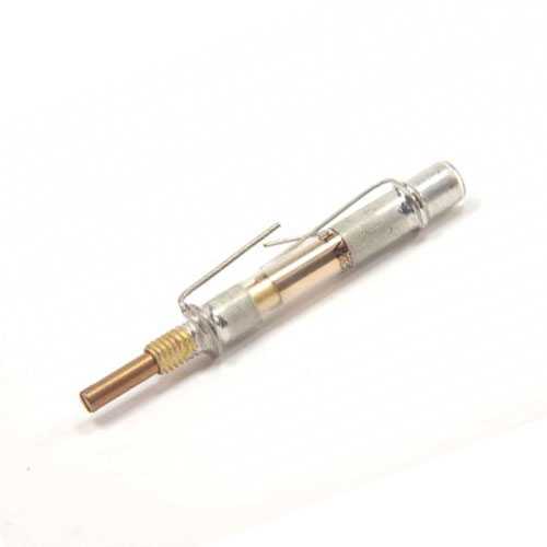
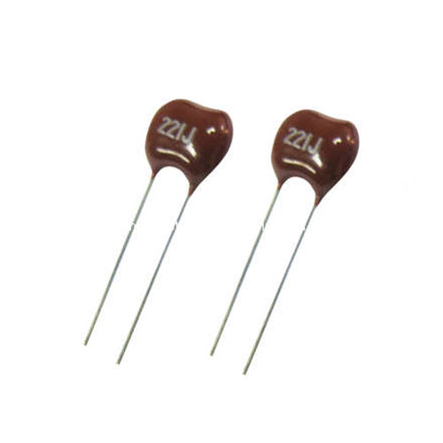
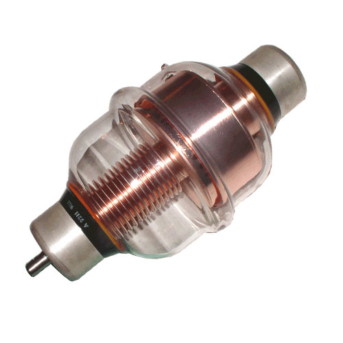
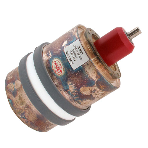
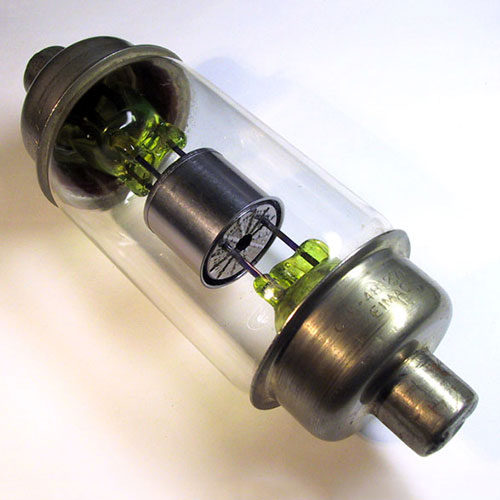
| Definition: Elemental capacitors are comprised of 3 types: Glass, Mica and Vacuum. Glass types have better stability and frequency than silver mica, is ultra-reliable, ultra-stable and resistant to nuclear radiation. Mica types have very high stability, with no aging and low losses. It is used for HF and low VHF, RF circuits. Vacuum types are utilised for extremely low losses, high voltage, high power RF applications and for transmitters and induction heating, also self-healing if the arc-over current is limited. |
| Definition: Elemental capacitors are comprised of 3 types: Glass, Mica and Vacuum. Glass types have better stability and frequency than silver mica, is ultra-reliable, ultra-stable and resistant to nuclear radiation. Mica types have very high stability, with no aging and low losses. It is used for HF and low VHF, RF circuits. Vacuum types are utilised for extremely low losses, high voltage, high power RF applications and for transmitters and induction heating, also self-healing if the arc-over current is limited. |
| Definition: Elemental capacitors are comprised of 3 types: Glass, Mica and Vacuum. Glass types have better stability and frequency than silver mica, is ultra-reliable, ultra-stable and resistant to nuclear radiation. Mica types have very high stability, with no aging and low losses. It is used for HF and low VHF, RF circuits. Vacuum types are utilised for extremely low losses, high voltage, high power RF applications and for transmitters and induction heating, also self-healing if the arc-over current is limited. |
| Definition: Elemental capacitors are comprised of 3 types: Glass, Mica and Vacuum. Glass types have better stability and frequency than silver mica, is ultra-reliable, ultra-stable and resistant to nuclear radiation. Mica types have very high stability, with no aging and low losses. It is used for HF and low VHF, RF circuits. Vacuum types are utilised for extremely low losses, high voltage, high power RF applications and for transmitters and induction heating, also self-healing if the arc-over current is limited. |
| Definition: Elemental capacitors are comprised of 3 types: Glass, Mica and Vacuum. Glass types have better stability and frequency than silver mica, is ultra-reliable, ultra-stable and resistant to nuclear radiation. Mica types have very high stability, with no aging and low losses. It is used for HF and low VHF, RF circuits. Vacuum types are utilised for extremely low losses, high voltage, high power RF applications and for transmitters and induction heating, also self-healing if the arc-over current is limited. |
| Elemental Glass |
 |
 |
 |
 |
| Elemental Glass |
|
|
|
|
| Elemental Glass |
|
|
|
|
| Elemental Glass |
|
|
|
|
| Elemental Glass |
|
|
|
|
| Elemental Mica |
 |
 |
 |
 |
| Elemental Mica |
|
|
|
|
| Elemental Mica |
|
|
|
|
| Elemental Mica |
|
|
|
|
| Elemental Mica |
|
|
|
|
| Elemental Vacuum |
 |
 |
 |
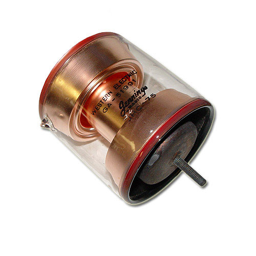 |
| Elemental Vacuum |
|
|
|
|
| Elemental Vacuum |
|
|
|
|
| Elemental Vacuum |
|
|
|
|
| Elemental Vacuum |
|
|
|
|
| Invented in 1909 by William Dubilier. |
| Invented in 1909 by William Dubilier. |
| Invented in 1909 by William Dubilier. |
| Invented in 1909 by William Dubilier. |
| Invented in 1909 by William Dubilier. |
 |
|
|
|
|
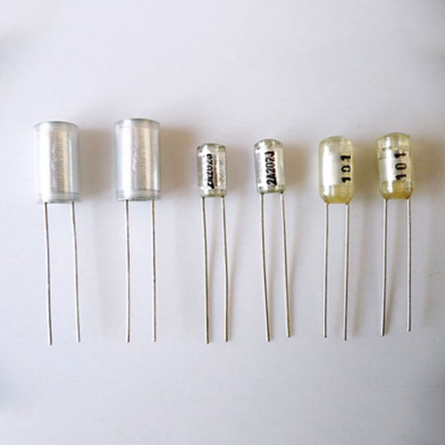
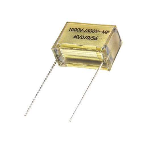
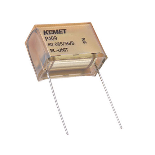
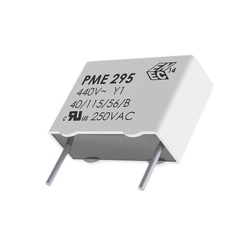
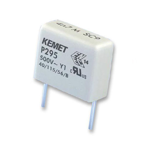
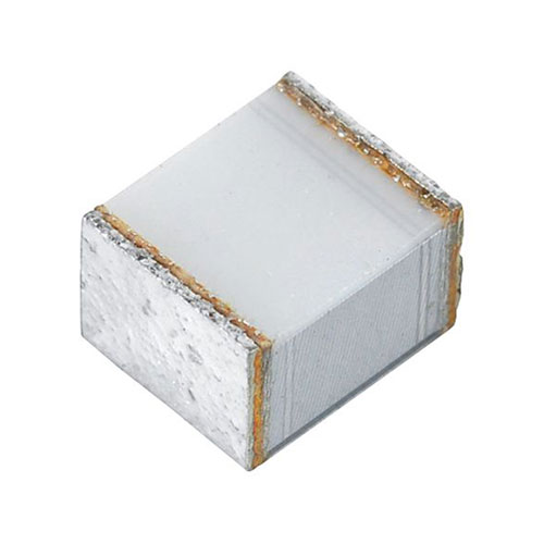
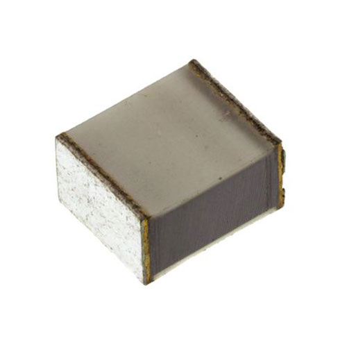
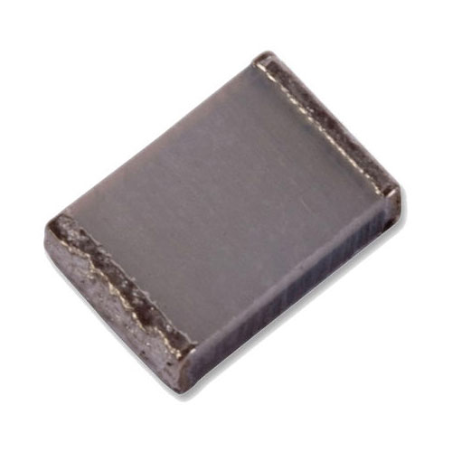
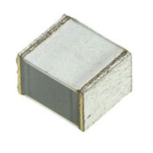
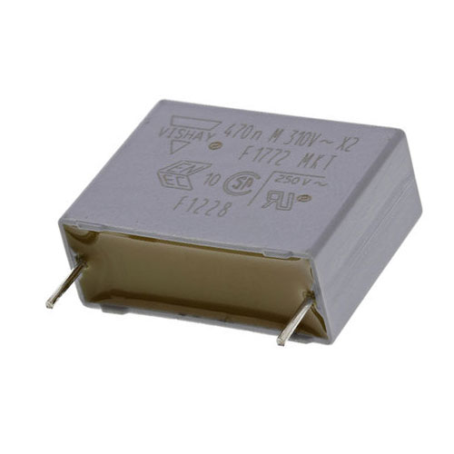
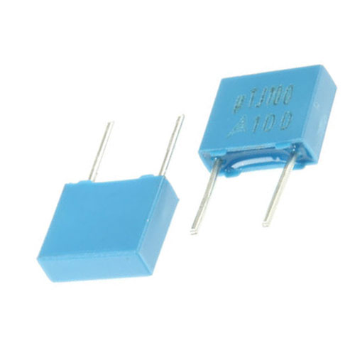
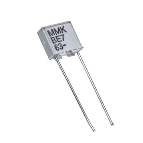
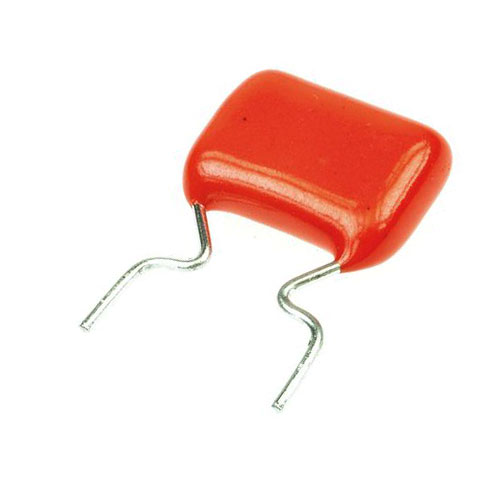
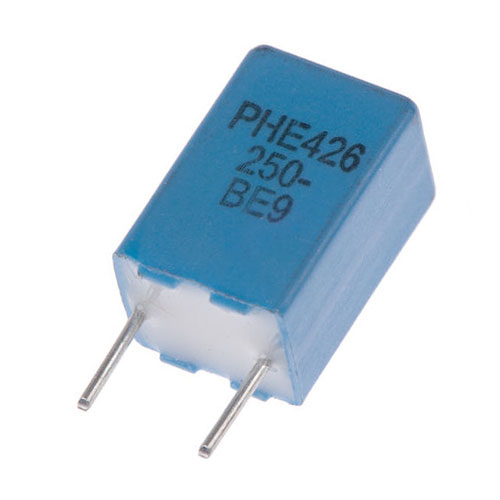
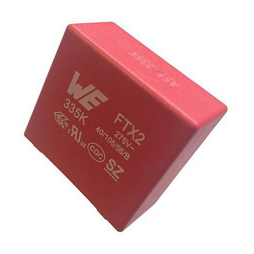
| Definition: Film capacitors have four main areas: Paper, PEN (Polyethylene Naphthalate), Polyester and Polypropylene. They possess an insulating plastic film as the dielectric, then drawn to a thin layer, provided with metallic electrodes and wound into a cylindrical winding. These electrodes are commonly metallised aluminium or zinc applied on one or both sides of the plastic film resulting in a metallised film capacitor that benefits from self-healing as shorts between the electrodes do not destroy the component. These film capacitors use two plastic films as the dielectric with each film covered with a thin metal foil, mostly aluminium, to form the electrodes. The advantage of this construction is the ease of connecting the metal foil electrodes, along with an excellent current pulse strength. The inherent geometry of film capacitor structure results in low ohmic losses and a low parasitic inductance, which makes them suitable for applications with high surge currents (snubbers) and for AC power applications, or for applications at higher frequencies. |
| Definition: Film capacitors have four main areas: Paper, PEN (Polyethylene Naphthalate), Polyester and Polypropylene. They possess an insulating plastic film as the dielectric, then drawn to a thin layer, provided with metallic electrodes and wound into a cylindrical winding. These electrodes are commonly metallised aluminium or zinc applied on one or both sides of the plastic film resulting in a metallised film capacitor that benefits from self-healing as shorts between the electrodes do not destroy the component. These film capacitors use two plastic films as the dielectric with each film covered with a thin metal foil, mostly aluminium, to form the electrodes. The advantage of this construction is the ease of connecting the metal foil electrodes, along with an excellent current pulse strength. The inherent geometry of film capacitor structure results in low ohmic losses and a low parasitic inductance, which makes them suitable for applications with high surge currents (snubbers) and for AC power applications, or for applications at higher frequencies. |
| Definition: Film capacitors have four main areas: Paper, PEN (Polyethylene Naphthalate), Polyester and Polypropylene. They possess an insulating plastic film as the dielectric, then drawn to a thin layer, provided with metallic electrodes and wound into a cylindrical winding. These electrodes are commonly metallised aluminium or zinc applied on one or both sides of the plastic film resulting in a metallised film capacitor that benefits from self-healing as shorts between the electrodes do not destroy the component. These film capacitors use two plastic films as the dielectric with each film covered with a thin metal foil, mostly aluminium, to form the electrodes. The advantage of this construction is the ease of connecting the metal foil electrodes, along with an excellent current pulse strength. The inherent geometry of film capacitor structure results in low ohmic losses and a low parasitic inductance, which makes them suitable for applications with high surge currents (snubbers) and for AC power applications, or for applications at higher frequencies. |
| Definition: Film capacitors have four main areas: Paper, PEN (Polyethylene Naphthalate), Polyester and Polypropylene. They possess an insulating plastic film as the dielectric, then drawn to a thin layer, provided with metallic electrodes and wound into a cylindrical winding. These electrodes are commonly metallised aluminium or zinc applied on one or both sides of the plastic film resulting in a metallised film capacitor that benefits from self-healing as shorts between the electrodes do not destroy the component. These film capacitors use two plastic films as the dielectric with each film covered with a thin metal foil, mostly aluminium, to form the electrodes. The advantage of this construction is the ease of connecting the metal foil electrodes, along with an excellent current pulse strength. The inherent geometry of film capacitor structure results in low ohmic losses and a low parasitic inductance, which makes them suitable for applications with high surge currents (snubbers) and for AC power applications, or for applications at higher frequencies. |
| Definition: Film capacitors have four main areas: Paper, PEN (Polyethylene Naphthalate), Polyester and Polypropylene. They possess an insulating plastic film as the dielectric, then drawn to a thin layer, provided with metallic electrodes and wound into a cylindrical winding. These electrodes are commonly metallised aluminium or zinc applied on one or both sides of the plastic film resulting in a metallised film capacitor that benefits from self-healing as shorts between the electrodes do not destroy the component. These film capacitors use two plastic films as the dielectric with each film covered with a thin metal foil, mostly aluminium, to form the electrodes. The advantage of this construction is the ease of connecting the metal foil electrodes, along with an excellent current pulse strength. The inherent geometry of film capacitor structure results in low ohmic losses and a low parasitic inductance, which makes them suitable for applications with high surge currents (snubbers) and for AC power applications, or for applications at higher frequencies. |
| Paper |
 |
 |
 |
 |
| Paper |
|
|
|
|
| Paper |
|
|
|
|
| Paper |
|
|
|
|
| Paper |
|
|
|
|
| PEN |
 |
 |
 |
 |
| PEN |
|
|
|
|
| PEN |
|
|
|
|
| PEN |
|
|
|
|
| PEN |
|
|
|
|
| Polyester |
 |
 |
 |
 |
| Polyester |
|
|
|
|
| Polyester |
|
|
|
|
| Polyester |
|
|
|
|
| Polyester |
|
|
|
|
| Polypropylene |
 |
 |
 |
 |
| Polypropylene |
|
|
|
|
| Polypropylene |
|
|
|
|
| Polypropylene |
|
|
|
|
| Polypropylene |
|
|
|
|
| Invented in 1876 by Desmond Gerald Fitzgerald. |
| Invented in 1876 by Desmond Gerald Fitzgerald. |
| Invented in 1876 by Desmond Gerald Fitzgerald. |
| Invented in 1876 by Desmond Gerald Fitzgerald. |
| Invented in 1876 by Desmond Gerald Fitzgerald. |
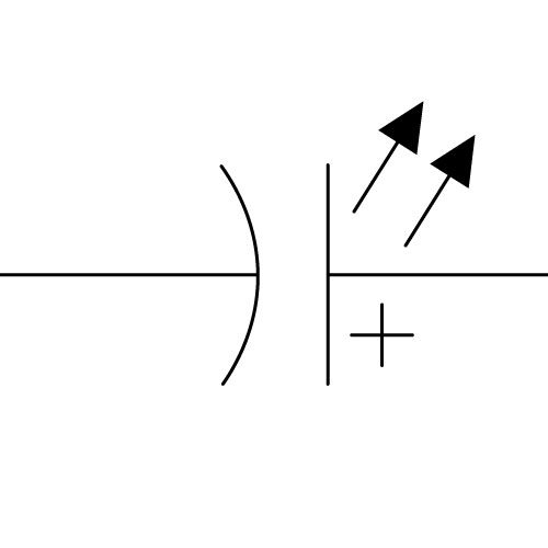
| Capacitor, Light Emitting |
| Capacitor, Light Emitting |
| Capacitor, Light Emitting |
| Capacitor, Light Emitting |
| Capacitor, Light Emitting |
 |
|
|
|
|
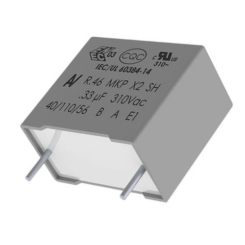
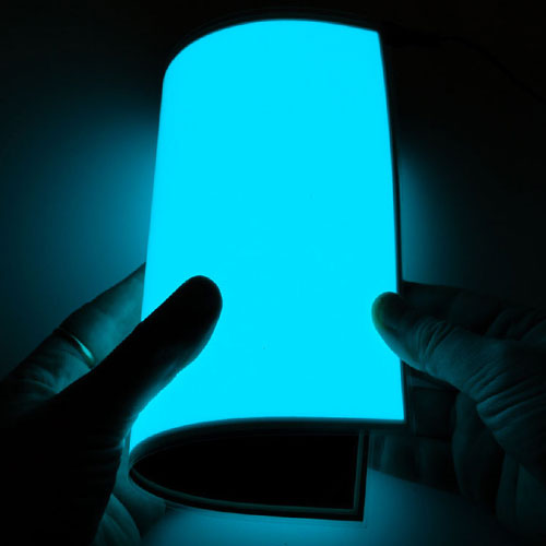
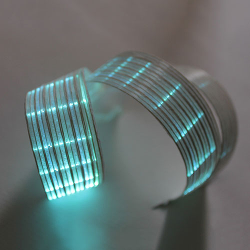
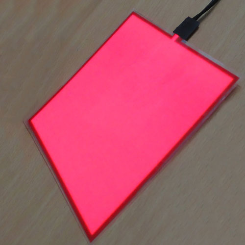
| Definition: The Light Emitting Capacitor (LEC), also known as an electroluminescent light source, produces light when phosphor crystals are excited by an electric current. Manufactured in layers of polyester films of Indium Tin Oxide, silver, phosphor, Barium Titanate (Dielectric) and carbon. Electroluminescent strips and panels are found in LCD backlights, wall, ceiling and strip lighting and is currently manufactured in 1 metre by 400 metre rolls. |
| Definition: The Light Emitting Capacitor (LEC), also known as an electroluminescent light source, produces light when phosphor crystals are excited by an electric current. Manufactured in layers of polyester films of Indium Tin Oxide, silver, phosphor, Barium Titanate (Dielectric) and carbon. Electroluminescent strips and panels are found in LCD backlights, wall, ceiling and strip lighting and is currently manufactured in 1 metre by 400 metre rolls. |
| Definition: The Light Emitting Capacitor (LEC), also known as an electroluminescent light source, produces light when phosphor crystals are excited by an electric current. Manufactured in layers of polyester films of Indium Tin Oxide, silver, phosphor, Barium Titanate (Dielectric) and carbon. Electroluminescent strips and panels are found in LCD backlights, wall, ceiling and strip lighting and is currently manufactured in 1 metre by 400 metre rolls. |
| Definition: The Light Emitting Capacitor (LEC), also known as an electroluminescent light source, produces light when phosphor crystals are excited by an electric current. Manufactured in layers of polyester films of Indium Tin Oxide, silver, phosphor, Barium Titanate (Dielectric) and carbon. Electroluminescent strips and panels are found in LCD backlights, wall, ceiling and strip lighting and is currently manufactured in 1 metre by 400 metre rolls. |
| Definition: The Light Emitting Capacitor (LEC), also known as an electroluminescent light source, produces light when phosphor crystals are excited by an electric current. Manufactured in layers of polyester films of Indium Tin Oxide, silver, phosphor, Barium Titanate (Dielectric) and carbon. Electroluminescent strips and panels are found in LCD backlights, wall, ceiling and strip lighting and is currently manufactured in 1 metre by 400 metre rolls. |
 |
 |
 |
 |
|
|
|
|
|
|
|
|
|
|
|
|
|
|
|
|
| Invented in 1936 by George Destriau. |
| Invented in 1936 by George Destriau. |
| Invented in 1936 by George Destriau. |
| Invented in 1936 by George Destriau. |
| Invented in 1936 by George Destriau. |
 |
|
|
|
|
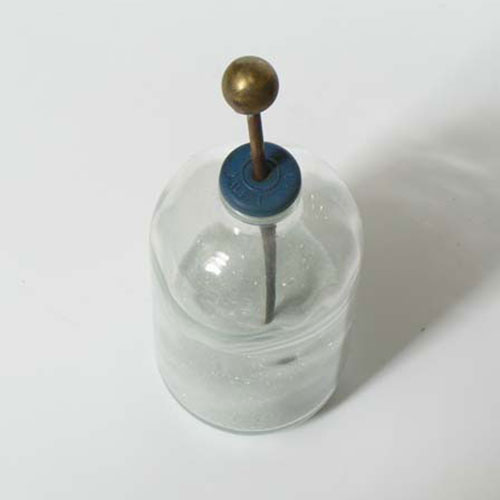
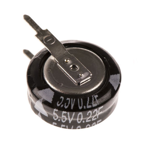
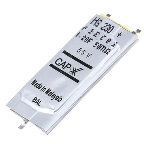
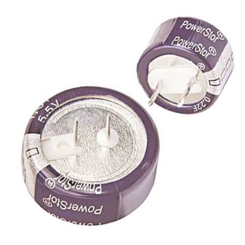
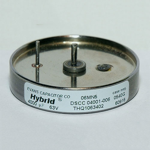
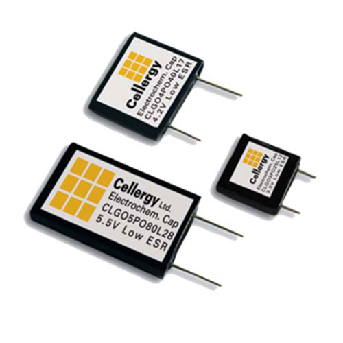
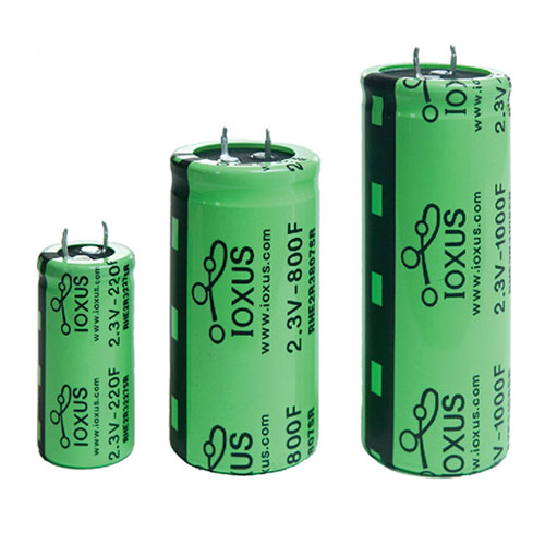
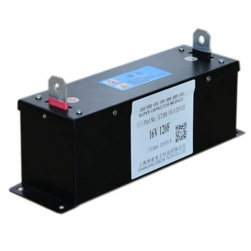
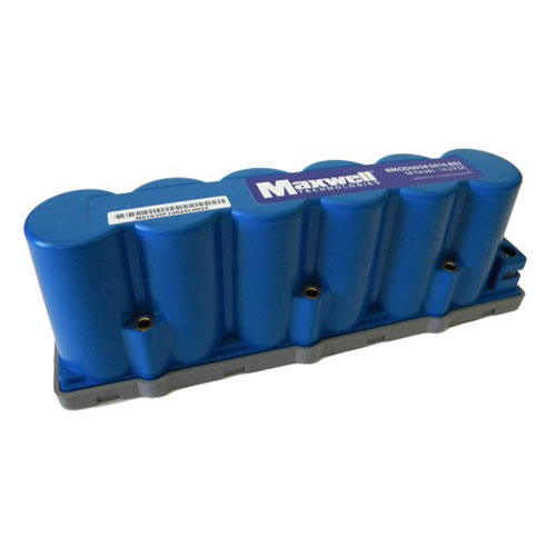
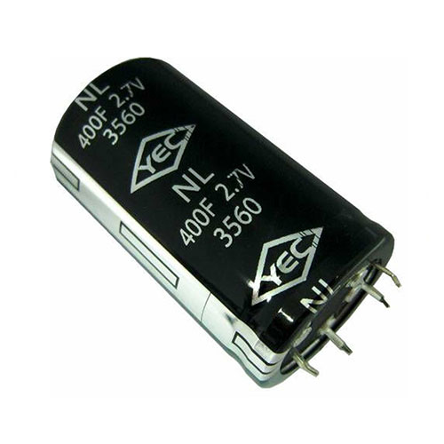
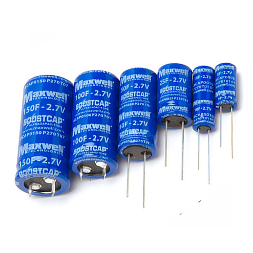
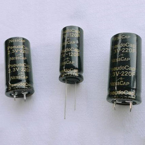
| Definition: Super capacitors have 3 distinct areas of development, Double Layer, Pseudo and Hybrid. They are from a family of electrochemical capacitors. Supercapacitors comprise of double-layer, pseudo and hybrid capacitors. Without a conventional solid dielectric, the capacitance of an electrochemical capacitor is determined by two storage principles, both of which contribute to the total capacitance of the capacitor. Storage is achieved by separation of charge in a Helmholtz double layer at the interface between the surface of a conductor and an electrolytic solution. The distance of separation of this electrostatic charge in a double-layer is on the order of 300 to 800 pm). Pseudocapacitance maintains storage achieved by redox reactions and intercalation on the surface of the electrode or by the adsorpted ions that results in a reversible faradaic charge-transfer. Supercapacitors are divided into three families, based on the design of the electrodes, Double-layer capacitors with carbon electrodes, Pseudocapacitors with electrodes of metal oxides or conducting polymers and Hybrid capacitors with asymmetric electrodes that exhibit both significant double-layer capacitance and pseudocapacitance, such as lithium-ion capacitors. Supercapacitors bridge the gap between conventional capacitors and rechargeable batteries and have the highest available capacitance values per unit volume of all capacitors. They support up to 12,000 Farads/1.2 Volt and whilst existing supercapacitors have energy densities at 10 percent of a conventional battery, their power density is 10 to 100 times greater and results in much shorter charge/discharge cycles than a battery is capable, and a greater tolerance for numerous charge/discharge cycles. This makes them well-suited for parallel connection with batteries, and may improve battery performance in terms of power density. |
| Definition: Super capacitors have 3 distinct areas of development, Double Layer, Pseudo and Hybrid. They are from a family of electrochemical capacitors. Supercapacitors comprise of double-layer, pseudo and hybrid capacitors. Without a conventional solid dielectric, the capacitance of an electrochemical capacitor is determined by two storage principles, both of which contribute to the total capacitance of the capacitor. Storage is achieved by separation of charge in a Helmholtz double layer at the interface between the surface of a conductor and an electrolytic solution. The distance of separation of this electrostatic charge in a double-layer is on the order of 300 to 800 pm). Pseudocapacitance maintains storage achieved by redox reactions and intercalation on the surface of the electrode or by the adsorpted ions that results in a reversible faradaic charge-transfer. Supercapacitors are divided into three families, based on the design of the electrodes, Double-layer capacitors with carbon electrodes, Pseudocapacitors with electrodes of metal oxides or conducting polymers and Hybrid capacitors with asymmetric electrodes that exhibit both significant double-layer capacitance and pseudocapacitance, such as lithium-ion capacitors. Supercapacitors bridge the gap between conventional capacitors and rechargeable batteries and have the highest available capacitance values per unit volume of all capacitors. They support up to 12,000 Farads/1.2 Volt and whilst existing supercapacitors have energy densities at 10 percent of a conventional battery, their power density is 10 to 100 times greater and results in much shorter charge/discharge cycles than a battery is capable, and a greater tolerance for numerous charge/discharge cycles. This makes them well-suited for parallel connection with batteries, and may improve battery performance in terms of power density. |
| Definition: Super capacitors have 3 distinct areas of development, Double Layer, Pseudo and Hybrid. They are from a family of electrochemical capacitors. Supercapacitors comprise of double-layer, pseudo and hybrid capacitors. Without a conventional solid dielectric, the capacitance of an electrochemical capacitor is determined by two storage principles, both of which contribute to the total capacitance of the capacitor. Storage is achieved by separation of charge in a Helmholtz double layer at the interface between the surface of a conductor and an electrolytic solution. The distance of separation of this electrostatic charge in a double-layer is on the order of 300 to 800 pm). Pseudocapacitance maintains storage achieved by redox reactions and intercalation on the surface of the electrode or by the adsorpted ions that results in a reversible faradaic charge-transfer. Supercapacitors are divided into three families, based on the design of the electrodes, Double-layer capacitors with carbon electrodes, Pseudocapacitors with electrodes of metal oxides or conducting polymers and Hybrid capacitors with asymmetric electrodes that exhibit both significant double-layer capacitance and pseudocapacitance, such as lithium-ion capacitors. Supercapacitors bridge the gap between conventional capacitors and rechargeable batteries and have the highest available capacitance values per unit volume of all capacitors. They support up to 12,000 Farads/1.2 Volt and whilst existing supercapacitors have energy densities at 10 percent of a conventional battery, their power density is 10 to 100 times greater and results in much shorter charge/discharge cycles than a battery is capable, and a greater tolerance for numerous charge/discharge cycles. This makes them well-suited for parallel connection with batteries, and may improve battery performance in terms of power density. |
| Definition: Super capacitors have 3 distinct areas of development, Double Layer, Pseudo and Hybrid. They are from a family of electrochemical capacitors. Supercapacitors comprise of double-layer, pseudo and hybrid capacitors. Without a conventional solid dielectric, the capacitance of an electrochemical capacitor is determined by two storage principles, both of which contribute to the total capacitance of the capacitor. Storage is achieved by separation of charge in a Helmholtz double layer at the interface between the surface of a conductor and an electrolytic solution. The distance of separation of this electrostatic charge in a double-layer is on the order of 300 to 800 pm). Pseudocapacitance maintains storage achieved by redox reactions and intercalation on the surface of the electrode or by the adsorpted ions that results in a reversible faradaic charge-transfer. Supercapacitors are divided into three families, based on the design of the electrodes, Double-layer capacitors with carbon electrodes, Pseudocapacitors with electrodes of metal oxides or conducting polymers and Hybrid capacitors with asymmetric electrodes that exhibit both significant double-layer capacitance and pseudocapacitance, such as lithium-ion capacitors. Supercapacitors bridge the gap between conventional capacitors and rechargeable batteries and have the highest available capacitance values per unit volume of all capacitors. They support up to 12,000 Farads/1.2 Volt and whilst existing supercapacitors have energy densities at 10 percent of a conventional battery, their power density is 10 to 100 times greater and results in much shorter charge/discharge cycles than a battery is capable, and a greater tolerance for numerous charge/discharge cycles. This makes them well-suited for parallel connection with batteries, and may improve battery performance in terms of power density. |
| Definition: Super capacitors have 3 distinct areas of development, Double Layer, Pseudo and Hybrid. They are from a family of electrochemical capacitors. Supercapacitors comprise of double-layer, pseudo and hybrid capacitors. Without a conventional solid dielectric, the capacitance of an electrochemical capacitor is determined by two storage principles, both of which contribute to the total capacitance of the capacitor. Storage is achieved by separation of charge in a Helmholtz double layer at the interface between the surface of a conductor and an electrolytic solution. The distance of separation of this electrostatic charge in a double-layer is on the order of 300 to 800 pm). Pseudocapacitance maintains storage achieved by redox reactions and intercalation on the surface of the electrode or by the adsorpted ions that results in a reversible faradaic charge-transfer. Supercapacitors are divided into three families, based on the design of the electrodes, Double-layer capacitors with carbon electrodes, Pseudocapacitors with electrodes of metal oxides or conducting polymers and Hybrid capacitors with asymmetric electrodes that exhibit both significant double-layer capacitance and pseudocapacitance, such as lithium-ion capacitors. Supercapacitors bridge the gap between conventional capacitors and rechargeable batteries and have the highest available capacitance values per unit volume of all capacitors. They support up to 12,000 Farads/1.2 Volt and whilst existing supercapacitors have energy densities at 10 percent of a conventional battery, their power density is 10 to 100 times greater and results in much shorter charge/discharge cycles than a battery is capable, and a greater tolerance for numerous charge/discharge cycles. This makes them well-suited for parallel connection with batteries, and may improve battery performance in terms of power density. |
| Double Layer |
 |
 |
 |
 |
| Double Layer |
|
|
|
|
| Double Layer |
|
|
|
|
| Double Layer |
|
|
|
|
| Double Layer |
|
|
|
|
| Hybrid |
 |
 |
 |
 |
| Hybrid |
|
|
|
|
| Hybrid |
|
|
|
|
| Hybrid |
|
|
|
|
| Hybrid |
|
|
|
|
| Pseudo |
 |
 |
 |
 |
| Pseudo |
|
|
|
|
| Pseudo |
|
|
|
|
| Pseudo |
|
|
|
|
| Pseudo |
|
|
|
|
| Invented in 1991 by Brian Evans Conway. |
| Invented in 1991 by Brian Evans Conway. |
| Invented in 1991 by Brian Evans Conway. |
| Invented in 1991 by Brian Evans Conway. |
| Invented in 1991 by Brian Evans Conway. |
 |
|
|
|
|
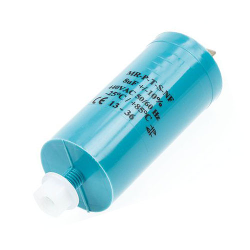
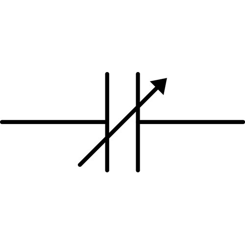
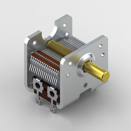
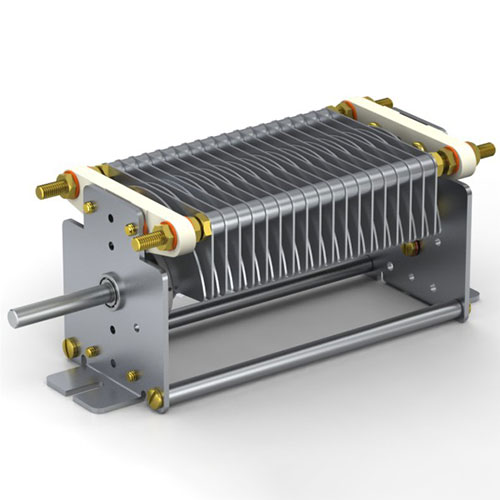
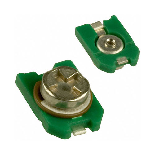
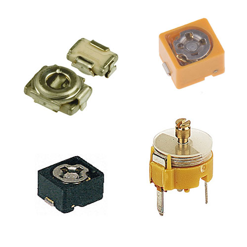
| Definition: Variable capacitors are an air capacitor and change capacitance by mechanical motion, two versions of variable capacitors are available, the tuning capacitor to select a wide capacitance range or a trimmer capacitor to fine tune a narrow band, usually for one-time oscillator circuit internal adjustments. Variable capacitors use a mechanical construction to change the distance between the plates or the amount of plate surface area will overlap and commonly use air as a dielectric medium. Variable capacitance diodes are now used to change capacitance as a function of the applied reverse bias voltage and are used like a variable capacitor and are favoured to replace tuning and trimmer capacitors. |
| Definition: Variable capacitors are an air capacitor and change capacitance by mechanical motion, two versions of variable capacitors are available, the tuning capacitor to select a wide capacitance range or a trimmer capacitor to fine tune a narrow band, usually for one-time oscillator circuit internal adjustments. Variable capacitors use a mechanical construction to change the distance between the plates or the amount of plate surface area will overlap and commonly use air as a dielectric medium. Variable capacitance diodes are now used to change capacitance as a function of the applied reverse bias voltage and are used like a variable capacitor and are favoured to replace tuning and trimmer capacitors. |
| Definition: Variable capacitors are an air capacitor and change capacitance by mechanical motion, two versions of variable capacitors are available, the tuning capacitor to select a wide capacitance range or a trimmer capacitor to fine tune a narrow band, usually for one-time oscillator circuit internal adjustments. Variable capacitors use a mechanical construction to change the distance between the plates or the amount of plate surface area will overlap and commonly use air as a dielectric medium. Variable capacitance diodes are now used to change capacitance as a function of the applied reverse bias voltage and are used like a variable capacitor and are favoured to replace tuning and trimmer capacitors. |
| Definition: Variable capacitors are an air capacitor and change capacitance by mechanical motion, two versions of variable capacitors are available, the tuning capacitor to select a wide capacitance range or a trimmer capacitor to fine tune a narrow band, usually for one-time oscillator circuit internal adjustments. Variable capacitors use a mechanical construction to change the distance between the plates or the amount of plate surface area will overlap and commonly use air as a dielectric medium. Variable capacitance diodes are now used to change capacitance as a function of the applied reverse bias voltage and are used like a variable capacitor and are favoured to replace tuning and trimmer capacitors. |
| Definition: Variable capacitors are an air capacitor and change capacitance by mechanical motion, two versions of variable capacitors are available, the tuning capacitor to select a wide capacitance range or a trimmer capacitor to fine tune a narrow band, usually for one-time oscillator circuit internal adjustments. Variable capacitors use a mechanical construction to change the distance between the plates or the amount of plate surface area will overlap and commonly use air as a dielectric medium. Variable capacitance diodes are now used to change capacitance as a function of the applied reverse bias voltage and are used like a variable capacitor and are favoured to replace tuning and trimmer capacitors. |
 |
 |
 |
 |
|
|
|
|
|
|
|
|
|
|
|
|
|
|
|
|
| Invented in 1893 by Dezső Korda. |
| Invented in 1893 by Dezső Korda. |
| Invented in 1893 by Dezső Korda. |
| Invented in 1893 by Dezső Korda. |
| Invented in 1893 by Dezső Korda. |
| CAPACITORS · INDUCTORS · TRANSFORMERS MEMRISTORS · RESISTORS · IDENTITY |
| CAPACITORS · INDUCTORS · TRANSFORMERS MEMRISTORS · RESISTORS · IDENTITY |
| CAPACITORS · INDUCTORS · TRANSFORMERS MEMRISTORS · RESISTORS · IDENTITY |
| CAPACITORS · INDUCTORS · TRANSFORMERS MEMRISTORS · RESISTORS · IDENTITY |
| CAPACITORS · INDUCTORS · TRANSFORMERS MEMRISTORS · RESISTORS · IDENTITY |
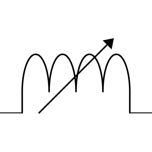
| Inductors, an overview |
| Inductors, an overview |
| Inductors, an overview |
| Inductors, an overview |
| Inductors, an overview |
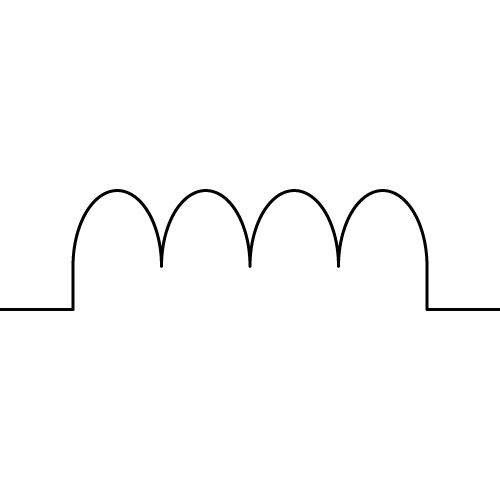
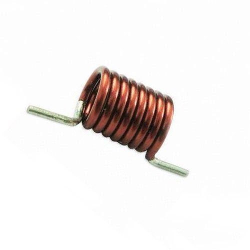
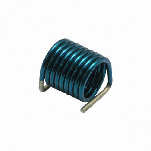
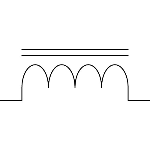
| Includes: Air, Ferromagnetic, and Variable. Definition: The Inductor, L, as 1 of 4 passive components, has 2 fundamental variables of Current and Flux. Measured in units of Inductance (Wb / A, or Henry), L = d Φm / dl. This electrical device is a wound spiral of two or more turns of insulated wire, used to introduce inductance into a circuit, produce a magnetic field from current flow, or to respond to a changing magnetic field by producing a voltage or mechanical motion, designed to provide a specific amount of inductance by the configuration of a coil with a core of either air or a combination of a nickel, iron, molybdenum, aluminium, silicon or boron. |
| Includes: Air, Ferromagnetic, and Variable. Definition: The Inductor, L, as 1 of 4 passive components, has 2 fundamental variables of Current and Flux. Measured in units of Inductance (Wb / A, or Henry), L = d Φm / dl. This electrical device is a wound spiral of two or more turns of insulated wire, used to introduce inductance into a circuit, produce a magnetic field from current flow, or to respond to a changing magnetic field by producing a voltage or mechanical motion, designed to provide a specific amount of inductance by the configuration of a coil with a core of either air or a combination of a nickel, iron, molybdenum, aluminium, silicon or boron. |
| Includes: Air, Ferromagnetic, and Variable. Definition: The Inductor, L, as 1 of 4 passive components, has 2 fundamental variables of Current and Flux. Measured in units of Inductance (Wb / A, or Henry), L = d Φm / dl. This electrical device is a wound spiral of two or more turns of insulated wire, used to introduce inductance into a circuit, produce a magnetic field from current flow, or to respond to a changing magnetic field by producing a voltage or mechanical motion, designed to provide a specific amount of inductance by the configuration of a coil with a core of either air or a combination of a nickel, iron, molybdenum, aluminium, silicon or boron. |
| Includes: Air, Ferromagnetic, and Variable. Definition: The Inductor, L, as 1 of 4 passive components, has 2 fundamental variables of Current and Flux. Measured in units of Inductance (Wb / A, or Henry), L = d Φm / dl. This electrical device is a wound spiral of two or more turns of insulated wire, used to introduce inductance into a circuit, produce a magnetic field from current flow, or to respond to a changing magnetic field by producing a voltage or mechanical motion, designed to provide a specific amount of inductance by the configuration of a coil with a core of either air or a combination of a nickel, iron, molybdenum, aluminium, silicon or boron. |
| Includes: Air, Ferromagnetic, and Variable. Definition: The Inductor, L, as 1 of 4 passive components, has 2 fundamental variables of Current and Flux. Measured in units of Inductance (Wb / A, or Henry), L = d Φm / dl. This electrical device is a wound spiral of two or more turns of insulated wire, used to introduce inductance into a circuit, produce a magnetic field from current flow, or to respond to a changing magnetic field by producing a voltage or mechanical motion, designed to provide a specific amount of inductance by the configuration of a coil with a core of either air or a combination of a nickel, iron, molybdenum, aluminium, silicon or boron. |
| Invented in 1831 by Michael Faraday. |
| Invented in 1831 by Michael Faraday. |
| Invented in 1831 by Michael Faraday. |
| Invented in 1831 by Michael Faraday. |
| Invented in 1831 by Michael Faraday. |
 |
|
|
|
|
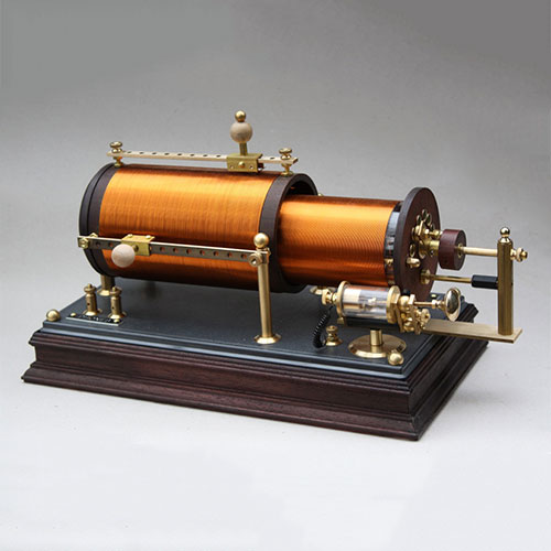
| Definition: Air inductors are a type of coil, that has an inductance that is unaffected by carrying current. Most radio transmitters rely on air coils to prevent the production of harmonics, they are free of “iron losses”, which affect ferromagnetic cores and as frequency is increased to as high as 1 GHz, the efficiency, Q-factor and power handling is improved with less distortion. Single layer inductors have an advantage of low self-capacitance and thus high self-resonant frequency. |
| Definition: Air inductors are a type of coil, that has an inductance that is unaffected by carrying current. Most radio transmitters rely on air coils to prevent the production of harmonics, they are free of “iron losses”, which affect ferromagnetic cores and as frequency is increased to as high as 1 GHz, the efficiency, Q-factor and power handling is improved with less distortion. Single layer inductors have an advantage of low self-capacitance and thus high self-resonant frequency. |
| Definition: Air inductors are a type of coil, that has an inductance that is unaffected by carrying current. Most radio transmitters rely on air coils to prevent the production of harmonics, they are free of “iron losses”, which affect ferromagnetic cores and as frequency is increased to as high as 1 GHz, the efficiency, Q-factor and power handling is improved with less distortion. Single layer inductors have an advantage of low self-capacitance and thus high self-resonant frequency. |
| Definition: Air inductors are a type of coil, that has an inductance that is unaffected by carrying current. Most radio transmitters rely on air coils to prevent the production of harmonics, they are free of “iron losses”, which affect ferromagnetic cores and as frequency is increased to as high as 1 GHz, the efficiency, Q-factor and power handling is improved with less distortion. Single layer inductors have an advantage of low self-capacitance and thus high self-resonant frequency. |
| Definition: Air inductors are a type of coil, that has an inductance that is unaffected by carrying current. Most radio transmitters rely on air coils to prevent the production of harmonics, they are free of “iron losses”, which affect ferromagnetic cores and as frequency is increased to as high as 1 GHz, the efficiency, Q-factor and power handling is improved with less distortion. Single layer inductors have an advantage of low self-capacitance and thus high self-resonant frequency. |
 |
 |
 |
 |
|
|
|
|
|
|
|
|
|
|
|
|
|
|
|
|
| Invented in 1831 by Michael Faraday. |
| Invented in 1831 by Michael Faraday. |
| Invented in 1831 by Michael Faraday. |
| Invented in 1831 by Michael Faraday. |
| Invented in 1831 by Michael Faraday. |
| Inductor, Ferromagnetic |
| Inductor, Ferromagnetic |
| Inductor, Ferromagnetic |
| Inductor, Ferromagnetic |
| Inductor, Ferromagnetic |
 |
|
|
|
|
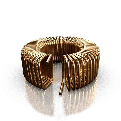
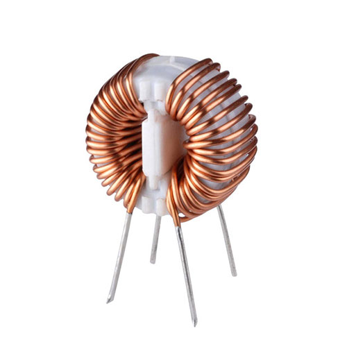
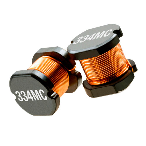
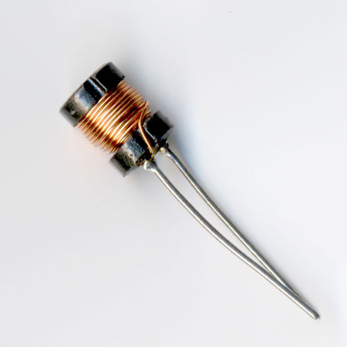
| Definition: Using an iron or ferrite core to increase the inductance, these inductors allow for a high inductance value with a limit of high frequency capacity due to hysteresis and eddy current losses. An increase the inductance of a coil by a factor of several thousand is achievable by utilising a magnetic core to increase the magnetic field. When an iron core is made with steel sheets, parallel to the magnetic field, the design, aims to block eddy currents between the plates, minimise energy losses and are primarily used for low frequencies in power transformer applications. |
| Definition: Using an iron or ferrite core to increase the inductance, these inductors allow for a high inductance value with a limit of high frequency capacity due to hysteresis and eddy current losses. An increase the inductance of a coil by a factor of several thousand is achievable by utilising a magnetic core to increase the magnetic field. When an iron core is made with steel sheets, parallel to the magnetic field, the design, aims to block eddy currents between the plates, minimise energy losses and are primarily used for low frequencies in power transformer applications. |
| Definition: Using an iron or ferrite core to increase the inductance, these inductors allow for a high inductance value with a limit of high frequency capacity due to hysteresis and eddy current losses. An increase the inductance of a coil by a factor of several thousand is achievable by utilising a magnetic core to increase the magnetic field. When an iron core is made with steel sheets, parallel to the magnetic field, the design, aims to block eddy currents between the plates, minimise energy losses and are primarily used for low frequencies in power transformer applications. |
| Definition: Using an iron or ferrite core to increase the inductance, these inductors allow for a high inductance value with a limit of high frequency capacity due to hysteresis and eddy current losses. An increase the inductance of a coil by a factor of several thousand is achievable by utilising a magnetic core to increase the magnetic field. When an iron core is made with steel sheets, parallel to the magnetic field, the design, aims to block eddy currents between the plates, minimise energy losses and are primarily used for low frequencies in power transformer applications. |
| Definition: Using an iron or ferrite core to increase the inductance, these inductors allow for a high inductance value with a limit of high frequency capacity due to hysteresis and eddy current losses. An increase the inductance of a coil by a factor of several thousand is achievable by utilising a magnetic core to increase the magnetic field. When an iron core is made with steel sheets, parallel to the magnetic field, the design, aims to block eddy currents between the plates, minimise energy losses and are primarily used for low frequencies in power transformer applications. |
 |
 |
 |
 |
|
|
|
|
|
|
|
|
|
|
|
|
|
|
|
|
| Invented in 1836 by Nicholas Callan. |
| Invented in 1836 by Nicholas Callan. |
| Invented in 1836 by Nicholas Callan. |
| Invented in 1836 by Nicholas Callan. |
| Invented in 1836 by Nicholas Callan. |
 |
|
|
|
|
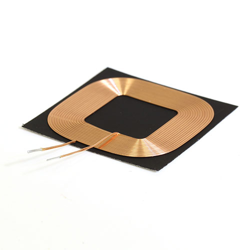
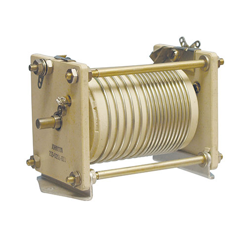
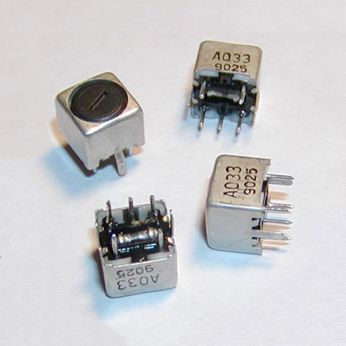
| Definition: Adjustable inductors vary impeding, shortening or maintaining length of the conductor. In a variometer, a pair of coils are arranged for one axis to be rotated relative to the other, altering their mutual inductance. When a magnetic field is present, in full or partial opposition, inductance cancellation results in negative mutual inductance. When this field is in addition, this will result in positive mutual inductance. When the axes of the two coils are at right angles, mutual inductance is zero. Roller inductors, have a conductor length that reduces as the inductance is reduced (unused turns are magnetically coupled) maintaining a minimum RF resistance and allowing for high Q at low inductance. Inductors with a stationary coil and internal arm, have the advantage of not requiring brush contacts for coil connections, resulting in a lower ESR than a roller inductor. |
| Definition: Adjustable inductors vary impeding, shortening or maintaining length of the conductor. In a variometer, a pair of coils are arranged for one axis to be rotated relative to the other, altering their mutual inductance. When a magnetic field is present, in full or partial opposition, inductance cancellation results in negative mutual inductance. When this field is in addition, this will result in positive mutual inductance. When the axes of the two coils are at right angles, mutual inductance is zero. Roller inductors, have a conductor length that reduces as the inductance is reduced (unused turns are magnetically coupled) maintaining a minimum RF resistance and allowing for high Q at low inductance. Inductors with a stationary coil and internal arm, have the advantage of not requiring brush contacts for coil connections, resulting in a lower ESR than a roller inductor. |
| Definition: Adjustable inductors vary impeding, shortening or maintaining length of the conductor. In a variometer, a pair of coils are arranged for one axis to be rotated relative to the other, altering their mutual inductance. When a magnetic field is present, in full or partial opposition, inductance cancellation results in negative mutual inductance. When this field is in addition, this will result in positive mutual inductance. When the axes of the two coils are at right angles, mutual inductance is zero. Roller inductors, have a conductor length that reduces as the inductance is reduced (unused turns are magnetically coupled) maintaining a minimum RF resistance and allowing for high Q at low inductance. Inductors with a stationary coil and internal arm, have the advantage of not requiring brush contacts for coil connections, resulting in a lower ESR than a roller inductor. |
| Definition: Adjustable inductors vary impeding, shortening or maintaining length of the conductor. In a variometer, a pair of coils are arranged for one axis to be rotated relative to the other, altering their mutual inductance. When a magnetic field is present, in full or partial opposition, inductance cancellation results in negative mutual inductance. When this field is in addition, this will result in positive mutual inductance. When the axes of the two coils are at right angles, mutual inductance is zero. Roller inductors, have a conductor length that reduces as the inductance is reduced (unused turns are magnetically coupled) maintaining a minimum RF resistance and allowing for high Q at low inductance. Inductors with a stationary coil and internal arm, have the advantage of not requiring brush contacts for coil connections, resulting in a lower ESR than a roller inductor. |
| Definition: Adjustable inductors vary impeding, shortening or maintaining length of the conductor. In a variometer, a pair of coils are arranged for one axis to be rotated relative to the other, altering their mutual inductance. When a magnetic field is present, in full or partial opposition, inductance cancellation results in negative mutual inductance. When this field is in addition, this will result in positive mutual inductance. When the axes of the two coils are at right angles, mutual inductance is zero. Roller inductors, have a conductor length that reduces as the inductance is reduced (unused turns are magnetically coupled) maintaining a minimum RF resistance and allowing for high Q at low inductance. Inductors with a stationary coil and internal arm, have the advantage of not requiring brush contacts for coil connections, resulting in a lower ESR than a roller inductor. |
 |
 |
 |
 |
|
|
|
|
|
|
|
|
|
|
|
|
|
|
|
|
| Invented in 1838 by Charles Grafton Page. |
| Invented in 1838 by Charles Grafton Page. |
| Invented in 1838 by Charles Grafton Page. |
| Invented in 1838 by Charles Grafton Page. |
| Invented in 1838 by Charles Grafton Page. |
| CAPACITORS · INDUCTORS · TRANSFORMERS MEMRISTORS · RESISTORS · IDENTITY |
| CAPACITORS · INDUCTORS · TRANSFORMERS MEMRISTORS · RESISTORS · IDENTITY |
| CAPACITORS · INDUCTORS · TRANSFORMERS MEMRISTORS · RESISTORS · IDENTITY |
| CAPACITORS · INDUCTORS · TRANSFORMERS MEMRISTORS · RESISTORS · IDENTITY |
| CAPACITORS · INDUCTORS · TRANSFORMERS MEMRISTORS · RESISTORS · IDENTITY |
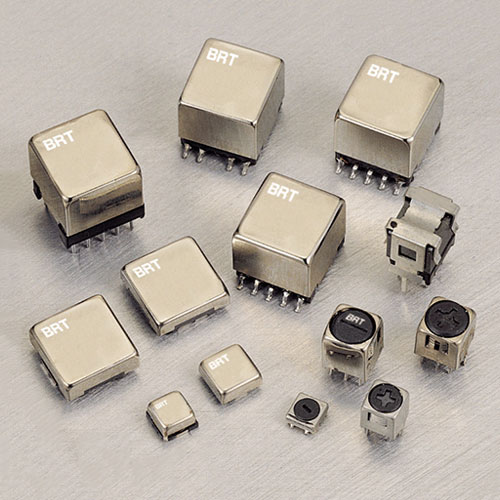
| Transformers, an overview |
| Transformers, an overview |
| Transformers, an overview |
| Transformers, an overview |
| Transformers, an overview |
| Includes: Auto, Centre-Tapped, Polyphase, Step, and Variable. Definition: A device used to transfer electric energy from one circuit to another, especially a pair of multiply wound, inductively coupled wire coils that effect such a transfer with a change in voltage, current, phase, or other electric characteristic. |
| Includes: Air, Ferromagnetic, and Variable. Definition: The Inductor, L, as 1 of 4 passive components, has 2 fundamental variables of Current and Flux. Measured in units of Inductance (Wb / A, or Henry), L = d Φm / dl. This electrical device is a wound spiral of two or more turns of insulated wire, used to introduce inductance into a circuit, produce a magnetic field from current flow, or to respond to a changing magnetic field by producing a voltage or mechanical motion, designed to provide a specific amount of inductance by the configuration of a coil with a core of either air or a combination of a nickel, iron, molybdenum, aluminium, silicon or boron. |
| Includes: Air, Ferromagnetic, and Variable. Definition: The Inductor, L, as 1 of 4 passive components, has 2 fundamental variables of Current and Flux. Measured in units of Inductance (Wb / A, or Henry), L = d Φm / dl. This electrical device is a wound spiral of two or more turns of insulated wire, used to introduce inductance into a circuit, produce a magnetic field from current flow, or to respond to a changing magnetic field by producing a voltage or mechanical motion, designed to provide a specific amount of inductance by the configuration of a coil with a core of either air or a combination of a nickel, iron, molybdenum, aluminium, silicon or boron. |
| Includes: Air, Ferromagnetic, and Variable. Definition: The Inductor, L, as 1 of 4 passive components, has 2 fundamental variables of Current and Flux. Measured in units of Inductance (Wb / A, or Henry), L = d Φm / dl. This electrical device is a wound spiral of two or more turns of insulated wire, used to introduce inductance into a circuit, produce a magnetic field from current flow, or to respond to a changing magnetic field by producing a voltage or mechanical motion, designed to provide a specific amount of inductance by the configuration of a coil with a core of either air or a combination of a nickel, iron, molybdenum, aluminium, silicon or boron. |
| Includes: Air, Ferromagnetic, and Variable. Definition: The Inductor, L, as 1 of 4 passive components, has 2 fundamental variables of Current and Flux. Measured in units of Inductance (Wb / A, or Henry), L = d Φm / dl. This electrical device is a wound spiral of two or more turns of insulated wire, used to introduce inductance into a circuit, produce a magnetic field from current flow, or to respond to a changing magnetic field by producing a voltage or mechanical motion, designed to provide a specific amount of inductance by the configuration of a coil with a core of either air or a combination of a nickel, iron, molybdenum, aluminium, silicon or boron. |
| Invented in 1836 by Nicholas Callan. |
| Invented in 1836 by Nicholas Callan. |
| Invented in 1836 by Nicholas Callan. |
| Invented in 1836 by Nicholas Callan. |
| Invented in 1836 by Nicholas Callan. |
| Core Types |
| AIR | DUST | FERRITE | LIQUID | SOLID |
| Core Types |
| AIR | DUST | FERRITE | LIQUID | SOLID |
| Core Types |
| AIR | DUST | FERRITE | LIQUID | SOLID |
| Core Types |
| AIR | DUST | FERRITE | LIQUID | SOLID |
| Core Types |
| AIR | DUST | FERRITE | LIQUID | SOLID |
| Definition: Continuous windings in both the input and output circuits. Used to step-down or step-up voltages to predetermined levels with limited losses, lower excitation current and increased KVA rating. |
| Definition: Continuous windings in both the input and output circuits. Used to step-down or step-up voltages to predetermined levels with limited losses, lower excitation current and increased KVA rating. |
| Definition: Continuous windings in both the input and output circuits. Used to step-down or step-up voltages to predetermined levels with limited losses, lower excitation current and increased KVA rating. |
| Definition: Continuous windings in both the input and output circuits. Used to step-down or step-up voltages to predetermined levels with limited losses, lower excitation current and increased KVA rating. |
| Definition: Continuous windings in both the input and output circuits. Used to step-down or step-up voltages to predetermined levels with limited losses, lower excitation current and increased KVA rating. |
|
|
|
|
|
|
|
|
|
|
| Transformer, Centre-Tapped |
| Transformer, Centre-Tapped |
| Transformer, Centre-Tapped |
| Transformer, Centre-Tapped |
| Transformer, Centre-Tapped |
| Definition: Possess shared electrically coupled properties of the secondary windings. |
| Definition: Possess shared electrically coupled properties of the secondary windings. |
| Definition: Possess shared electrically coupled properties of the secondary windings. |
| Definition: Possess shared electrically coupled properties of the secondary windings. |
| Definition: Possess shared electrically coupled properties of the secondary windings. |
|
|
|
|
|
|
|
|
|
|
| Transformer, Polyphase |
| Transformer, Polyphase |
| Transformer, Polyphase |
| Transformer, Polyphase |
| Transformer, Polyphase |
| Definition: Multiple Step Transformers with identical primary and/or secondary windings which can be configured in Star (Υ) with an additional common connection, allowing for multiple voltages i.e. 415 and 240, or Delta (Δ) configurations, Υ Υ, Υ Δ, Δ Υ or Δ Δ. |
| Definition: Multiple Step Transformers with identical primary and/or secondary windings which can be configured in Star (Υ) with an additional common connection, allowing for multiple voltages i.e. 415 and 240, or Delta (Δ) configurations, Υ Υ, Υ Δ, Δ Υ or Δ Δ. |
| Definition: Multiple Step Transformers with identical primary and/or secondary windings which can be configured in Star (Υ) with an additional common connection, allowing for multiple voltages i.e. 415 and 240, or Delta (Δ) configurations, Υ Υ, Υ Δ, Δ Υ or Δ Δ. |
| Definition: Multiple Step Transformers with identical primary and/or secondary windings which can be configured in Star (Υ) with an additional common connection, allowing for multiple voltages i.e. 415 and 240, or Delta (Δ) configurations, Υ Υ, Υ Δ, Δ Υ or Δ Δ. |
| Definition: Multiple Step Transformers with identical primary and/or secondary windings which can be configured in Star (Υ) with an additional common connection, allowing for multiple voltages i.e. 415 and 240, or Delta (Δ) configurations, Υ Υ, Υ Δ, Δ Υ or Δ Δ. |
|
|
|
|
|
|
|
|
|
|
| Definition: Comprised of three different types that are dependent on the primary to secondary winding ratios: Step Up Transformers have a greater secondary winding percentage, Step Down Transformers have a greater primary winding percentage. The third, Isolation Transformers, have identical primary and secondary windings. |
| Definition: Comprised of three different types that are dependent on the primary to secondary winding ratios: Step Up Transformers have a greater secondary winding percentage, Step Down Transformers have a greater primary winding percentage. The third, Isolation Transformers, have identical primary and secondary windings. |
| Definition: Comprised of three different types that are dependent on the primary to secondary winding ratios: Step Up Transformers have a greater secondary winding percentage, Step Down Transformers have a greater primary winding percentage. The third, Isolation Transformers, have identical primary and secondary windings. |
| Definition: Comprised of three different types that are dependent on the primary to secondary winding ratios: Step Up Transformers have a greater secondary winding percentage, Step Down Transformers have a greater primary winding percentage. The third, Isolation Transformers, have identical primary and secondary windings. |
| Definition: Comprised of three different types that are dependent on the primary to secondary winding ratios: Step Up Transformers have a greater secondary winding percentage, Step Down Transformers have a greater primary winding percentage. The third, Isolation Transformers, have identical primary and secondary windings. |
|
|
|
|
|
|
|
|
|
|
| Transformer, Variable |
| Transformer, Variable |
| Transformer, Variable |
| Transformer, Variable |
| Transformer, Variable |
| Definition: Defined as any transformer with windings that can be calibrated or adjusted without interfering with core type, insulator or conductor properties. |
| Definition: Defined as any transformer with windings that can be calibrated or adjusted without interfering with core type, insulator or conductor properties. |
| Definition: Defined as any transformer with windings that can be calibrated or adjusted without interfering with core type, insulator or conductor properties. |
| Definition: Defined as any transformer with windings that can be calibrated or adjusted without interfering with core type, insulator or conductor properties. |
| Definition: Defined as any transformer with windings that can be calibrated or adjusted without interfering with core type, insulator or conductor properties. |
|
|
|
|
|
|
|
|
|
|
| CAPACITORS · INDUCTORS · TRANSFORMERS MEMRISTORS · RESISTORS · IDENTITY |
| CAPACITORS · INDUCTORS · TRANSFORMERS MEMRISTORS · RESISTORS · IDENTITY |
| CAPACITORS · INDUCTORS · TRANSFORMERS MEMRISTORS · RESISTORS · IDENTITY |
| CAPACITORS · INDUCTORS · TRANSFORMERS MEMRISTORS · RESISTORS · IDENTITY |
| CAPACITORS · INDUCTORS · TRANSFORMERS MEMRISTORS · RESISTORS · IDENTITY |
| Memristors, an overview |
| Memristors, an overview |
| Memristors, an overview |
| Memristors, an overview |
| Memristors, an overview |
 |
|
|
|
|
| Definition: The Memristor, M, as 1 of 4 passive components, has 2 fundamental variables of Flux and Charge. Measured in units of Memristance (Wb / C, or Ohms), M = d Φm / dq. Discovered in 1971 by Leon Chua, Physicist, Memristors are a fundamental switch that remembers the last electrical state. This junction, built on a layer of Platinum (Pt), has a layer of “resistive”, Titanium Dioxide (TiO2), with an upper layer of oxygen deficient, “conductive”, Titanium Dioxide (TiO2-x) and is capped with an upper layer of Platinum. When a positive voltage is applied, oxygen vacancies in the top layer of TiO2-x are repelled into the lower layer of Ti O2, inverting the polarity of the junction and turns the memristor on. By applying a negative voltage, oxygen vacancies are repelled to the top layer and turns the memristor on, creating a perfect binary bit. A memristor device, as a passive, non-volatile memory, is built from a matrix of memristor junctions formed by crossbars of the TiO2 and TiO2-x materials and providing voltage to vectors, encoding a 2 or 3 dimensional device. |
| Definition: The Memristor, M, as 1 of 4 passive components, has 2 fundamental variables of Flux and Charge. Measured in units of Memristance (Wb / C, or Ohms), M = d Φm / dq. Discovered in 1971 by Leon Chua, Physicist, Memristors are a fundamental switch that remembers the last electrical state. This junction, built on a layer of Platinum (Pt), has a layer of “resistive”, Titanium Dioxide (TiO2), with an upper layer of oxygen deficient, “conductive”, Titanium Dioxide (TiO2-x) and is capped with an upper layer of Platinum. When a positive voltage is applied, oxygen vacancies in the top layer of TiO2-x are repelled into the lower layer of Ti O2, inverting the polarity of the junction and turns the memristor on. By applying a negative voltage, oxygen vacancies are repelled to the top layer and turns the memristor on, creating a perfect binary bit. A memristor device, as a passive, non-volatile memory, is built from a matrix of memristor junctions formed by crossbars of the TiO2 and TiO2-x materials and providing voltage to vectors, encoding a 2 or 3 dimensional device. |
| Definition: The Memristor, M, as 1 of 4 passive components, has 2 fundamental variables of Flux and Charge. Measured in units of Memristance (Wb / C, or Ohms), M = d Φm / dq. Discovered in 1971 by Leon Chua, Physicist, Memristors are a fundamental switch that remembers the last electrical state. This junction, built on a layer of Platinum (Pt), has a layer of “resistive”, Titanium Dioxide (TiO2), with an upper layer of oxygen deficient, “conductive”, Titanium Dioxide (TiO2-x) and is capped with an upper layer of Platinum. When a positive voltage is applied, oxygen vacancies in the top layer of TiO2-x are repelled into the lower layer of Ti O2, inverting the polarity of the junction and turns the memristor on. By applying a negative voltage, oxygen vacancies are repelled to the top layer and turns the memristor on, creating a perfect binary bit. A memristor device, as a passive, non-volatile memory, is built from a matrix of memristor junctions formed by crossbars of the TiO2 and TiO2-x materials and providing voltage to vectors, encoding a 2 or 3 dimensional device. |
| Definition: The Memristor, M, as 1 of 4 passive components, has 2 fundamental variables of Flux and Charge. Measured in units of Memristance (Wb / C, or Ohms), M = d Φm / dq. Discovered in 1971 by Leon Chua, Physicist, Memristors are a fundamental switch that remembers the last electrical state. This junction, built on a layer of Platinum (Pt), has a layer of “resistive”, Titanium Dioxide (TiO2), with an upper layer of oxygen deficient, “conductive”, Titanium Dioxide (TiO2-x) and is capped with an upper layer of Platinum. When a positive voltage is applied, oxygen vacancies in the top layer of TiO2-x are repelled into the lower layer of Ti O2, inverting the polarity of the junction and turns the memristor on. By applying a negative voltage, oxygen vacancies are repelled to the top layer and turns the memristor on, creating a perfect binary bit. A memristor device, as a passive, non-volatile memory, is built from a matrix of memristor junctions formed by crossbars of the TiO2 and TiO2-x materials and providing voltage to vectors, encoding a 2 or 3 dimensional device. |
| Definition: The Memristor, M, as 1 of 4 passive components, has 2 fundamental variables of Flux and Charge. Measured in units of Memristance (Wb / C, or Ohms), M = d Φm / dq. Discovered in 1971 by Leon Chua, Physicist, Memristors are a fundamental switch that remembers the last electrical state. This junction, built on a layer of Platinum (Pt), has a layer of “resistive”, Titanium Dioxide (TiO2), with an upper layer of oxygen deficient, “conductive”, Titanium Dioxide (TiO2-x) and is capped with an upper layer of Platinum. When a positive voltage is applied, oxygen vacancies in the top layer of TiO2-x are repelled into the lower layer of Ti O2, inverting the polarity of the junction and turns the memristor on. By applying a negative voltage, oxygen vacancies are repelled to the top layer and turns the memristor on, creating a perfect binary bit. A memristor device, as a passive, non-volatile memory, is built from a matrix of memristor junctions formed by crossbars of the TiO2 and TiO2-x materials and providing voltage to vectors, encoding a 2 or 3 dimensional device. |
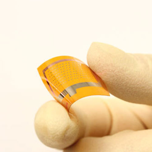 |
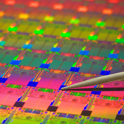 |
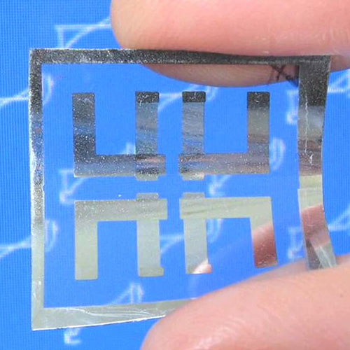 |
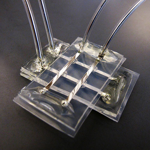 |
|
|
|
|
|
|
|
|
|
|
|
|
|
|
|
|
| Invented in 2006 by Stanley Williams. |
| Invented in 2006 by Stanley Williams. |
| Invented in 2006 by Stanley Williams. |
| Invented in 2006 by Stanley Williams. |
| Invented in 2006 by Stanley Williams. |
| CAPACITORS · INDUCTORS · TRANSFORMERS MEMRISTORS · RESISTORS · IDENTITY |
| CAPACITORS · INDUCTORS · TRANSFORMERS MEMRISTORS · RESISTORS · IDENTITY |
| CAPACITORS · INDUCTORS · TRANSFORMERS MEMRISTORS · RESISTORS · IDENTITY |
| CAPACITORS · INDUCTORS · TRANSFORMERS MEMRISTORS · RESISTORS · IDENTITY |
| CAPACITORS · INDUCTORS · TRANSFORMERS MEMRISTORS · RESISTORS · IDENTITY |
| Resistors, an overview |
| Resistors, an overview |
| Resistors, an overview |
| Resistors, an overview |
| Resistors, an overview |
| Includes: Fixed, Force Sensitive, High Voltage, Humistor, Light Dependent, Network, Power, RF, Thermistor, and Variable. Definition: Resistors, as 1 of 4 passive components, have 2 fundamental variables of Voltage and Current. Measured in units of Resistance (V / A or Ohms, Ω), R = dV / dl). Resistors add electrical resistance to a circuit and are used to reduce current flow or divide voltages within a circuit. They can be used as a logical reference to encode or control power distribution systems, electromechanical devices and communication systems. Tolerance, as a percentage, is the accuracy of the fixed value of a resistor is determined by the material choice, Carbon Composite with 5% to 20%, Carbon Film with 1% to 5%, Wire Wound with 0.005% to 5%, Metal Film with 0.1 to 1% and Foil Resistors with 0.1% to 0.0005%. TCR, Resistivity, Conductivity and Temperature Coefficient of various materials at 20 °C (68 °F, 293 K) can be found as a reference on this site. Resistor Colour Codes can be found as a reference on this site. |
| Includes: Fixed, Force Sensitive, High Voltage, Humistor, Light Dependent, Network, Power, RF, Thermistor, and Variable. Definition: Resistors, as 1 of 4 passive components, have 2 fundamental variables of Voltage and Current. Measured in units of Resistance (V / A or Ohms, Ω), R = dV / dl). Resistors add electrical resistance to a circuit and are used to reduce current flow or divide voltages within a circuit. They can be used as a logical reference to encode or control power distribution systems, electromechanical devices and communication systems. Tolerance, as a percentage, is the accuracy of the fixed value of a resistor is determined by the material choice, Carbon Composite with 5% to 20%, Carbon Film with 1% to 5%, Wire Wound with 0.005% to 5%, Metal Film with 0.1 to 1% and Foil Resistors with 0.1% to 0.0005%. TCR, Resistivity, Conductivity and Temperature Coefficient of various materials at 20 °C (68 °F, 293 K) can be found as a reference on this site. Resistor Colour Codes can be found as a reference on this site. |
| Includes: Fixed, Force Sensitive, High Voltage, Humistor, Light Dependent, Network, Power, RF, Thermistor, and Variable. Definition: Resistors, as 1 of 4 passive components, have 2 fundamental variables of Voltage and Current. Measured in units of Resistance (V / A or Ohms, Ω), R = dV / dl). Resistors add electrical resistance to a circuit and are used to reduce current flow or divide voltages within a circuit. They can be used as a logical reference to encode or control power distribution systems, electromechanical devices and communication systems. Tolerance, as a percentage, is the accuracy of the fixed value of a resistor is determined by the material choice, Carbon Composite with 5% to 20%, Carbon Film with 1% to 5%, Wire Wound with 0.005% to 5%, Metal Film with 0.1 to 1% and Foil Resistors with 0.1% to 0.0005%. TCR, Resistivity, Conductivity and Temperature Coefficient of various materials at 20 °C (68 °F, 293 K) can be found as a reference on this site. Resistor Colour Codes can be found as a reference on this site. |
| Includes: Fixed, Force Sensitive, High Voltage, Humistor, Light Dependent, Network, Power, RF, Thermistor, and Variable. Definition: Resistors, as 1 of 4 passive components, have 2 fundamental variables of Voltage and Current. Measured in units of Resistance (V / A or Ohms, Ω), R = dV / dl). Resistors add electrical resistance to a circuit and are used to reduce current flow or divide voltages within a circuit. They can be used as a logical reference to encode or control power distribution systems, electromechanical devices and communication systems. Tolerance, as a percentage, is the accuracy of the fixed value of a resistor is determined by the material choice, Carbon Composite with 5% to 20%, Carbon Film with 1% to 5%, Wire Wound with 0.005% to 5%, Metal Film with 0.1 to 1% and Foil Resistors with 0.1% to 0.0005%. TCR, Resistivity, Conductivity and Temperature Coefficient of various materials at 20 °C (68 °F, 293 K) can be found as a reference on this site. Resistor Colour Codes can be found as a reference on this site. |
| Includes: Fixed, Force Sensitive, High Voltage, Humistor, Light Dependent, Network, Power, RF, Thermistor, and Variable. Definition: Resistors, as 1 of 4 passive components, have 2 fundamental variables of Voltage and Current. Measured in units of Resistance (V / A or Ohms, Ω), R = dV / dl). Resistors add electrical resistance to a circuit and are used to reduce current flow or divide voltages within a circuit. They can be used as a logical reference to encode or control power distribution systems, electromechanical devices and communication systems. Tolerance, as a percentage, is the accuracy of the fixed value of a resistor is determined by the material choice, Carbon Composite with 5% to 20%, Carbon Film with 1% to 5%, Wire Wound with 0.005% to 5%, Metal Film with 0.1 to 1% and Foil Resistors with 0.1% to 0.0005%. TCR, Resistivity, Conductivity and Temperature Coefficient of various materials at 20 °C (68 °F, 293 K) can be found as a reference on this site. Resistor Colour Codes can be found as a reference on this site. |
| Invented in 1827 by Georg Simon Ohm. |
| Invented in 1827 by Georg Simon Ohm. |
| Invented in 1827 by Georg Simon Ohm. |
| Invented in 1827 by Georg Simon Ohm. |
| Invented in 1827 by Georg Simon Ohm. |
 |
|
|
|
|
| Definition: Fixed resistors are not adjustable and are the most commonly used resistors and electronic components. With the difficulty of constant ohmic resistance independent of frequency, voltage or temperature, is why there are a great many materials developed for fixed resistive devices, achieving accuracies of 0.000’5 percent tolerance. |
| Definition: Fixed resistors are not adjustable and are the most commonly used resistors and electronic components. With the difficulty of constant ohmic resistance independent of frequency, voltage or temperature, is why there are a great many materials developed for fixed resistive devices, achieving accuracies of 0.000’5 percent tolerance. |
| Definition: Fixed resistors are not adjustable and are the most commonly used resistors and electronic components. With the difficulty of constant ohmic resistance independent of frequency, voltage or temperature, is why there are a great many materials developed for fixed resistive devices, achieving accuracies of 0.000’5 percent tolerance. |
| Definition: Fixed resistors are not adjustable and are the most commonly used resistors and electronic components. With the difficulty of constant ohmic resistance independent of frequency, voltage or temperature, is why there are a great many materials developed for fixed resistive devices, achieving accuracies of 0.000’5 percent tolerance. |
| Definition: Fixed resistors are not adjustable and are the most commonly used resistors and electronic components. With the difficulty of constant ohmic resistance independent of frequency, voltage or temperature, is why there are a great many materials developed for fixed resistive devices, achieving accuracies of 0.000’5 percent tolerance. |
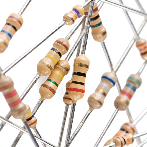 |
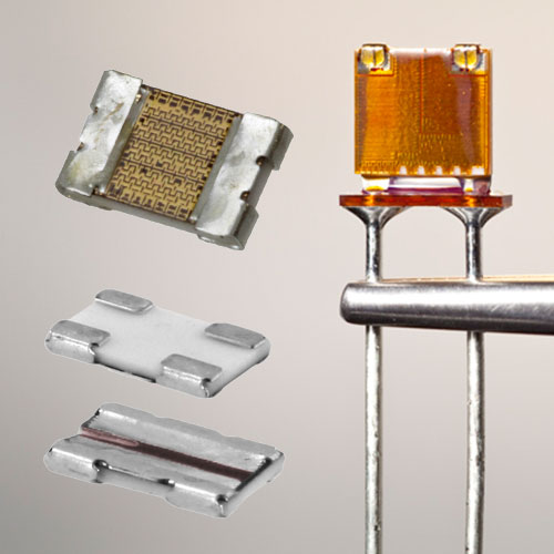 |
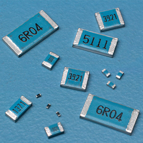 |
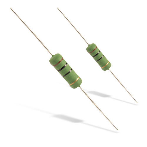 |
|
|
|
|
|
|
|
|
|
|
|
|
|
|
|
|
| Invented in 1827 by Georg Simon Ohm. |
| Invented in 1827 by Georg Simon Ohm. |
| Invented in 1827 by Georg Simon Ohm. |
| Invented in 1827 by Georg Simon Ohm. |
| Invented in 1827 by Georg Simon Ohm. |
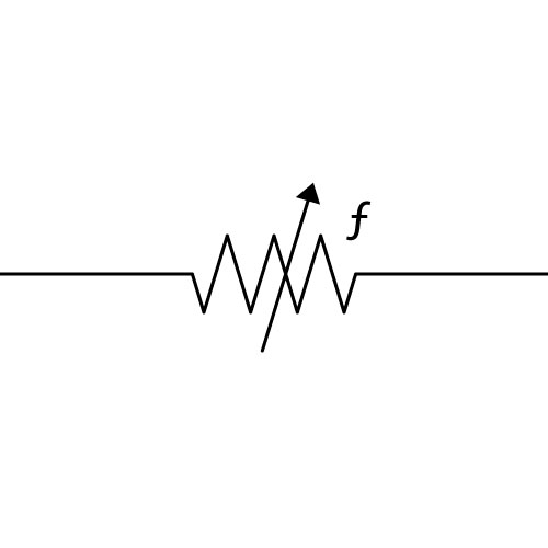 |
|
|
|
|
| Definition: The force sensitive (force-sensing) resistor is a flexible material which progressively changes resistance when a force or pressure is applied. Consisting of a conductive polymer as a sensing film with both electrically conducting and non-conducting particles suspended in matrix and are formulated to resist temperature dependence, the force to the sensing film causes particles to touch the conducting electrodes, progressively increasing resistance of the film. |
| Definition: The force sensitive (force-sensing) resistor is a flexible material which progressively changes resistance when a force or pressure is applied. Consisting of a conductive polymer as a sensing film with both electrically conducting and non-conducting particles suspended in matrix and are formulated to resist temperature dependence, the force to the sensing film causes particles to touch the conducting electrodes, progressively increasing resistance of the film. |
| Definition: The force sensitive (force-sensing) resistor is a flexible material which progressively changes resistance when a force or pressure is applied. Consisting of a conductive polymer as a sensing film with both electrically conducting and non-conducting particles suspended in matrix and are formulated to resist temperature dependence, the force to the sensing film causes particles to touch the conducting electrodes, progressively increasing resistance of the film. |
| Definition: The force sensitive (force-sensing) resistor is a flexible material which progressively changes resistance when a force or pressure is applied. Consisting of a conductive polymer as a sensing film with both electrically conducting and non-conducting particles suspended in matrix and are formulated to resist temperature dependence, the force to the sensing film causes particles to touch the conducting electrodes, progressively increasing resistance of the film. |
| Definition: The force sensitive (force-sensing) resistor is a flexible material which progressively changes resistance when a force or pressure is applied. Consisting of a conductive polymer as a sensing film with both electrically conducting and non-conducting particles suspended in matrix and are formulated to resist temperature dependence, the force to the sensing film causes particles to touch the conducting electrodes, progressively increasing resistance of the film. |
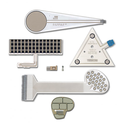 |
 |
 |
 |
|
|
|
|
|
|
|
|
|
|
|
|
|
|
|
|
| Invented in 1977 by Franklin Eventoff. |
| Invented in 1977 by Franklin Eventoff. |
| Invented in 1977 by Franklin Eventoff. |
| Invented in 1977 by Franklin Eventoff. |
| Invented in 1977 by Franklin Eventoff. |
| Resistor, High Voltage |
| Resistor, High Voltage |
| Resistor, High Voltage |
| Resistor, High Voltage |
| Resistor, High Voltage |
 |
|
|
|
|
| Definition: With edge wound resistors of up to 4 kilowatts, grid resistors approaching 100 kilowatts and large scale resistors of up to 500 megawatts requiring extensive load banks, dynamic breaking, heatsinks, cooling towers, and cryogenics for the transfer of junction temperatures to heat exchangers to reclaim energy. |
| Definition: With edge wound resistors of up to 4 kilowatts, grid resistors approaching 100 kilowatts and large scale resistors of up to 500 megawatts requiring extensive load banks, dynamic breaking, heatsinks, cooling towers, and cryogenics for the transfer of junction temperatures to heat exchangers to reclaim energy. |
| Definition: With edge wound resistors of up to 4 kilowatts, grid resistors approaching 100 kilowatts and large scale resistors of up to 500 megawatts requiring extensive load banks, dynamic breaking, heatsinks, cooling towers, and cryogenics for the transfer of junction temperatures to heat exchangers to reclaim energy. |
| Definition: With edge wound resistors of up to 4 kilowatts, grid resistors approaching 100 kilowatts and large scale resistors of up to 500 megawatts requiring extensive load banks, dynamic breaking, heatsinks, cooling towers, and cryogenics for the transfer of junction temperatures to heat exchangers to reclaim energy. |
| Definition: With edge wound resistors of up to 4 kilowatts, grid resistors approaching 100 kilowatts and large scale resistors of up to 500 megawatts requiring extensive load banks, dynamic breaking, heatsinks, cooling towers, and cryogenics for the transfer of junction temperatures to heat exchangers to reclaim energy. |
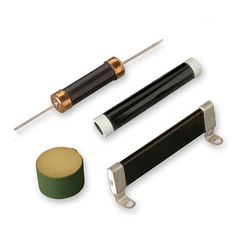 |
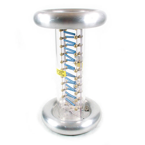 |
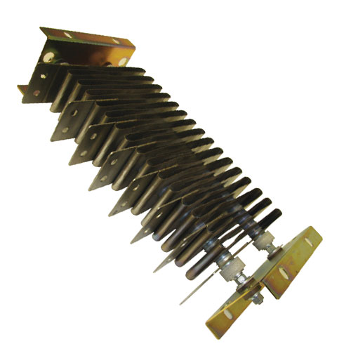 |
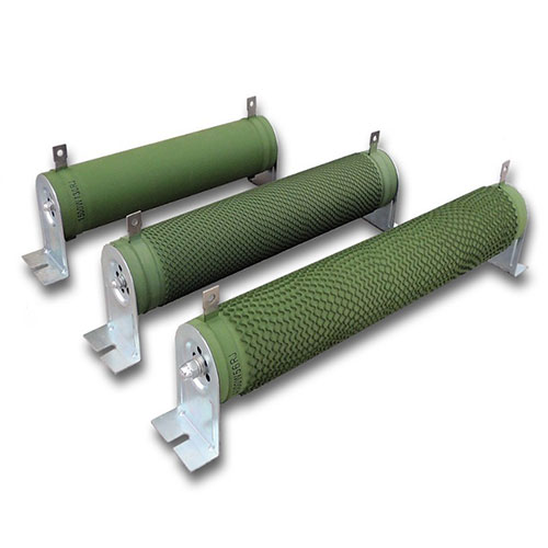 |
|
|
|
|
|
|
|
|
|
|
|
|
|
|
|
|
| Invented in 1827 by Georg Simon Ohm. |
| Invented in 1827 by Georg Simon Ohm. |
| Invented in 1827 by Georg Simon Ohm. |
| Invented in 1827 by Georg Simon Ohm. |
| Invented in 1827 by Georg Simon Ohm. |
 |
|
|
|
|
| Definition: Humidity sensing resistor with a ceramic composition of polyamide resin, polyvinyl chloride, polyethylene, or a metal oxide and detects relative humidity by measuring a change in the resistance of an electrolytic, polymeric, or metallic oxide sensor element. |
| Definition: Humidity sensing resistor with a ceramic composition of polyamide resin, polyvinyl chloride, polyethylene, or a metal oxide and detects relative humidity by measuring a change in the resistance of an electrolytic, polymeric, or metallic oxide sensor element. |
| Definition: Humidity sensing resistor with a ceramic composition of polyamide resin, polyvinyl chloride, polyethylene, or a metal oxide and detects relative humidity by measuring a change in the resistance of an electrolytic, polymeric, or metallic oxide sensor element. |
| Definition: Humidity sensing resistor with a ceramic composition of polyamide resin, polyvinyl chloride, polyethylene, or a metal oxide and detects relative humidity by measuring a change in the resistance of an electrolytic, polymeric, or metallic oxide sensor element. |
| Definition: Humidity sensing resistor with a ceramic composition of polyamide resin, polyvinyl chloride, polyethylene, or a metal oxide and detects relative humidity by measuring a change in the resistance of an electrolytic, polymeric, or metallic oxide sensor element. |
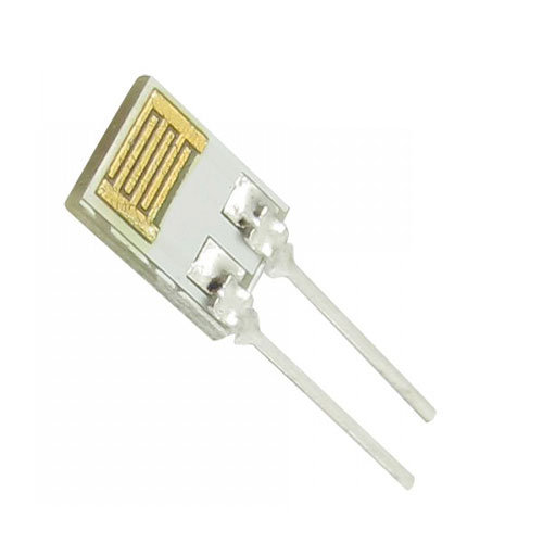 |
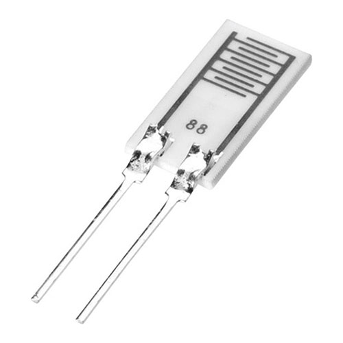 |
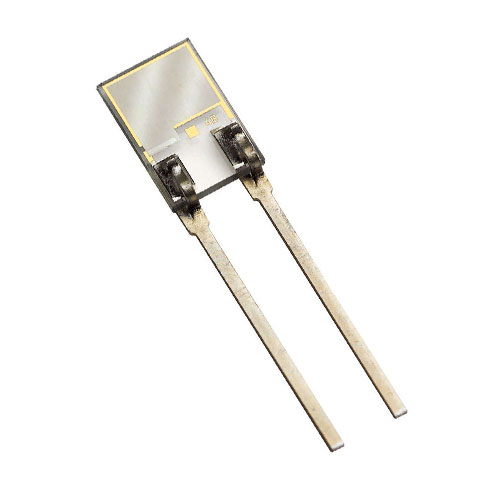 |
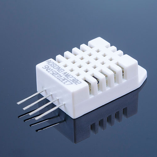 |
|
|
|
|
|
|
|
|
|
|
|
|
|
|
|
|
| Invented in 1974 by Anthony Fraioli & Lawrence E Frazee. |
| Invented in 1974 by Anthony Fraioli & Lawrence E Frazee. |
| Invented in 1974 by Anthony Fraioli & Lawrence E Frazee. |
| Invented in 1974 by Anthony Fraioli & Lawrence E Frazee. |
| Invented in 1974 by Anthony Fraioli & Lawrence E Frazee. |
| Resistor, Light Dependent |
| Resistor, Light Dependent |
| Resistor, Light Dependent |
| Resistor, Light Dependent |
| Resistor, Light Dependent |
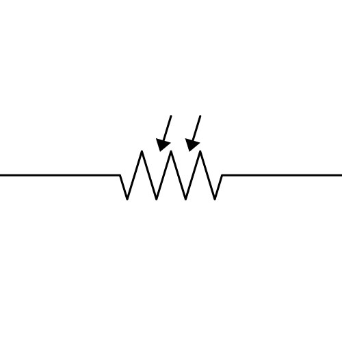 |
|
|
|
|
| Definition: The light dependent resistor, LDR or photoresistor, exhibit an increase in conductivity (fall in resistance) when lighting levels increase. Intrinsic photoresistors use semiconductor materials that are un-doped and include silicon or germanium. Photons excite electrons moving away from the valence to the conduction band, resulting in lower resistance, as electrons that are free to conduct electricity. The later extrinsic photoresistors, are manufactured from materials that are doped with impurities (dopants) to create a higher energy band. |
| Definition: The light dependent resistor, LDR or photoresistor, exhibit an increase in conductivity (fall in resistance) when lighting levels increase. Intrinsic photoresistors use semiconductor materials that are un-doped and include silicon or germanium. Photons excite electrons moving away from the valence to the conduction band, resulting in lower resistance, as electrons that are free to conduct electricity. The later extrinsic photoresistors, are manufactured from materials that are doped with impurities (dopants) to create a higher energy band. |
| Definition: The light dependent resistor, LDR or photoresistor, exhibit an increase in conductivity (fall in resistance) when lighting levels increase. Intrinsic photoresistors use semiconductor materials that are un-doped and include silicon or germanium. Photons excite electrons moving away from the valence to the conduction band, resulting in lower resistance, as electrons that are free to conduct electricity. The later extrinsic photoresistors, are manufactured from materials that are doped with impurities (dopants) to create a higher energy band. |
| Definition: The light dependent resistor, LDR or photoresistor, exhibit an increase in conductivity (fall in resistance) when lighting levels increase. Intrinsic photoresistors use semiconductor materials that are un-doped and include silicon or germanium. Photons excite electrons moving away from the valence to the conduction band, resulting in lower resistance, as electrons that are free to conduct electricity. The later extrinsic photoresistors, are manufactured from materials that are doped with impurities (dopants) to create a higher energy band. |
| Definition: The light dependent resistor, LDR or photoresistor, exhibit an increase in conductivity (fall in resistance) when lighting levels increase. Intrinsic photoresistors use semiconductor materials that are un-doped and include silicon or germanium. Photons excite electrons moving away from the valence to the conduction band, resulting in lower resistance, as electrons that are free to conduct electricity. The later extrinsic photoresistors, are manufactured from materials that are doped with impurities (dopants) to create a higher energy band. |
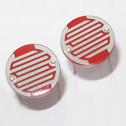 |
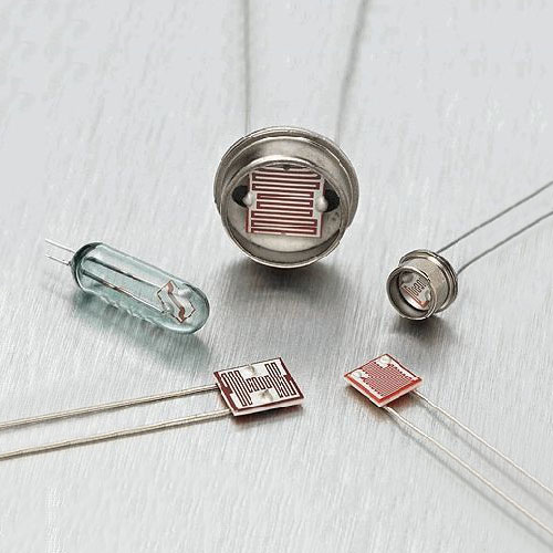 |
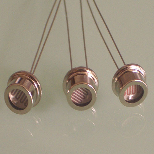 |
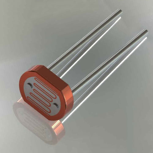 |
|
|
|
|
|
|
|
|
|
|
|
|
|
|
|
|
| Invented in 1952 by Bernard Rollin. |
| Invented in 1952 by Bernard Rollin. |
| Invented in 1952 by Bernard Rollin. |
| Invented in 1952 by Bernard Rollin. |
| Invented in 1952 by Bernard Rollin. |
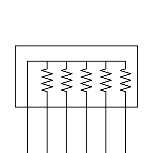 |
|
|
|
|
| Definition: The first resistor network was first constructed in what is now known as the Wheatstone bridge, which is a circuit consisting of 4 resistors, whereby an unknown value of a resistor may be known by using a galvanometer to balance the current flowing through the network and mathematics. British scientist, Wheatstone, came across the instrument and gave an account to the Royal Society of London, regarding the lecture given by Samuel Christie in 1843, however it soon came to be called the Wheatstone bridge. |
| Definition: The first resistor network was first constructed in what is now known as the Wheatstone bridge, which is a circuit consisting of 4 resistors, whereby an unknown value of a resistor may be known by using a galvanometer to balance the current flowing through the network and mathematics. British scientist, Wheatstone, came across the instrument and gave an account to the Royal Society of London, regarding the lecture given by Samuel Christie in 1843, however it soon came to be called the Wheatstone bridge. |
| Definition: The first resistor network was first constructed in what is now known as the Wheatstone bridge, which is a circuit consisting of 4 resistors, whereby an unknown value of a resistor may be known by using a galvanometer to balance the current flowing through the network and mathematics. British scientist, Wheatstone, came across the instrument and gave an account to the Royal Society of London, regarding the lecture given by Samuel Christie in 1843, however it soon came to be called the Wheatstone bridge. |
| Definition: The first resistor network was first constructed in what is now known as the Wheatstone bridge, which is a circuit consisting of 4 resistors, whereby an unknown value of a resistor may be known by using a galvanometer to balance the current flowing through the network and mathematics. British scientist, Wheatstone, came across the instrument and gave an account to the Royal Society of London, regarding the lecture given by Samuel Christie in 1843, however it soon came to be called the Wheatstone bridge. |
| Definition: The first resistor network was first constructed in what is now known as the Wheatstone bridge, which is a circuit consisting of 4 resistors, whereby an unknown value of a resistor may be known by using a galvanometer to balance the current flowing through the network and mathematics. British scientist, Wheatstone, came across the instrument and gave an account to the Royal Society of London, regarding the lecture given by Samuel Christie in 1843, however it soon came to be called the Wheatstone bridge. |
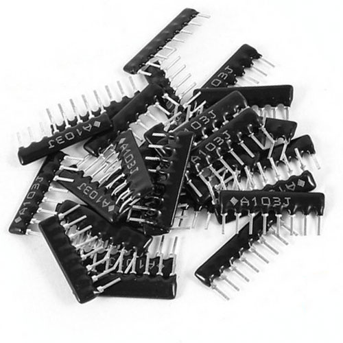 |
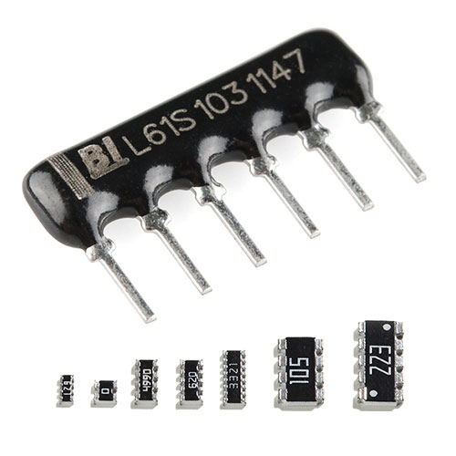 |
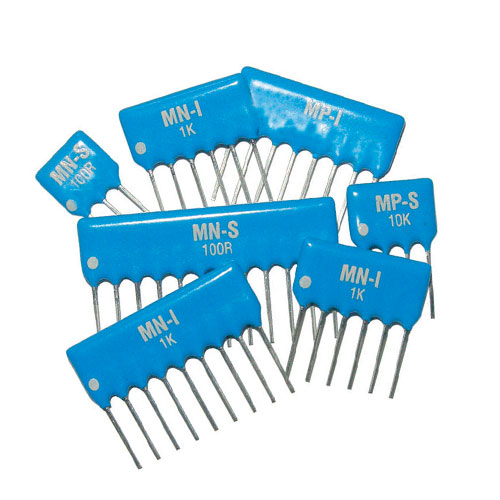 |
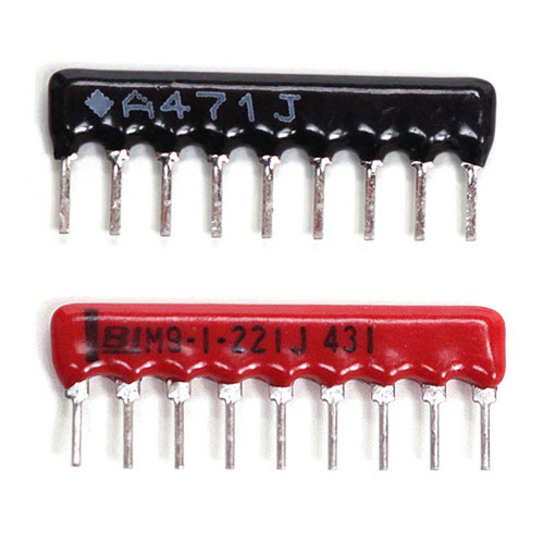 |
|
|
|
|
|
|
|
|
|
|
|
|
|
|
|
|
| Invented in 1833 by Samuel Hunter Christie. |
| Invented in 1833 by Samuel Hunter Christie. |
| Invented in 1833 by Samuel Hunter Christie. |
| Invented in 1833 by Samuel Hunter Christie. |
| Invented in 1833 by Samuel Hunter Christie. |
 |
|
|
|
|
| Definition: Most electronics applications use low power quarter watt resistors. Requirements for power supplies, power conversion, amplifiers, and heaters, demand high power resistors which are rated from 1 watt through to a kilowatts of power. On average, the capabilities of radial, SMD, and ceramic power transistors can reach up to 10 watts, thick film, wirewound and current sense resistors reach 100 watts. |
| Definition: Most electronics applications use low power quarter watt resistors. Requirements for power supplies, power conversion, amplifiers, and heaters, demand high power resistors which are rated from 1 watt through to a kilowatts of power. On average, the capabilities of radial, SMD, and ceramic power transistors can reach up to 10 watts, thick film, wirewound and current sense resistors reach 100 watts. |
| Definition: Most electronics applications use low power quarter watt resistors. Requirements for power supplies, power conversion, amplifiers, and heaters, demand high power resistors which are rated from 1 watt through to a kilowatts of power. On average, the capabilities of radial, SMD, and ceramic power transistors can reach up to 10 watts, thick film, wirewound and current sense resistors reach 100 watts. |
| Definition: Most electronics applications use low power quarter watt resistors. Requirements for power supplies, power conversion, amplifiers, and heaters, demand high power resistors which are rated from 1 watt through to a kilowatts of power. On average, the capabilities of radial, SMD, and ceramic power transistors can reach up to 10 watts, thick film, wirewound and current sense resistors reach 100 watts. |
| Definition: Most electronics applications use low power quarter watt resistors. Requirements for power supplies, power conversion, amplifiers, and heaters, demand high power resistors which are rated from 1 watt through to a kilowatts of power. On average, the capabilities of radial, SMD, and ceramic power transistors can reach up to 10 watts, thick film, wirewound and current sense resistors reach 100 watts. |
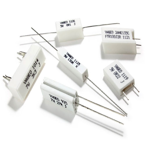 |
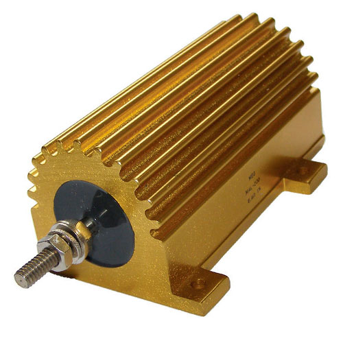 |
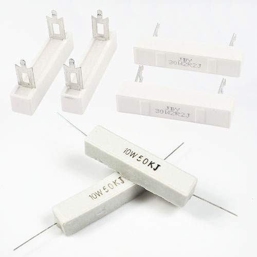 |
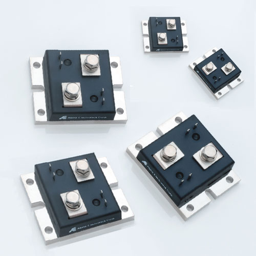 |
|
|
|
|
|
|
|
|
|
|
|
|
|
|
|
|
| Invented in 1861 by Otis Boykin. |
| Invented in 1861 by Otis Boykin. |
| Invented in 1861 by Otis Boykin. |
| Invented in 1861 by Otis Boykin. |
| Invented in 1861 by Otis Boykin. |
 |
|
|
|
|
| Definition: RF resistors are primarily brazed, High Power Resistors, Attenuators and Terminations for Microwaves and RF applications. In demanding environments, high temperature brazing can yield the lowest thermal resistance at higher temperatures. Packaging is traditionally surface and flange with aluminium, aluminium nitrate and beryllium oxide substrates. Power ratings range from 30 milliwatts to 1 kilowatt at frequencies approaching 100 gigahertz and resistance of 10 to 1,000 ohms. |
| Definition: RF resistors are primarily brazed, High Power Resistors, Attenuators and Terminations for Microwaves and RF applications. In demanding environments, high temperature brazing can yield the lowest thermal resistance at higher temperatures. Packaging is traditionally surface and flange with aluminium, aluminium nitrate and beryllium oxide substrates. Power ratings range from 30 milliwatts to 1 kilowatt at frequencies approaching 100 gigahertz and resistance of 10 to 1,000 ohms. |
| Definition: RF resistors are primarily brazed, High Power Resistors, Attenuators and Terminations for Microwaves and RF applications. In demanding environments, high temperature brazing can yield the lowest thermal resistance at higher temperatures. Packaging is traditionally surface and flange with aluminium, aluminium nitrate and beryllium oxide substrates. Power ratings range from 30 milliwatts to 1 kilowatt at frequencies approaching 100 gigahertz and resistance of 10 to 1,000 ohms. |
| Definition: RF resistors are primarily brazed, High Power Resistors, Attenuators and Terminations for Microwaves and RF applications. In demanding environments, high temperature brazing can yield the lowest thermal resistance at higher temperatures. Packaging is traditionally surface and flange with aluminium, aluminium nitrate and beryllium oxide substrates. Power ratings range from 30 milliwatts to 1 kilowatt at frequencies approaching 100 gigahertz and resistance of 10 to 1,000 ohms. |
| Definition: RF resistors are primarily brazed, High Power Resistors, Attenuators and Terminations for Microwaves and RF applications. In demanding environments, high temperature brazing can yield the lowest thermal resistance at higher temperatures. Packaging is traditionally surface and flange with aluminium, aluminium nitrate and beryllium oxide substrates. Power ratings range from 30 milliwatts to 1 kilowatt at frequencies approaching 100 gigahertz and resistance of 10 to 1,000 ohms. |
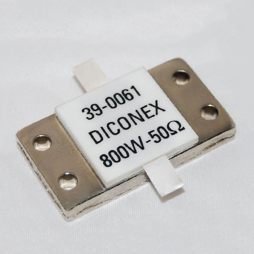 |
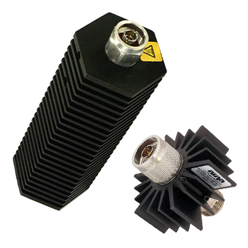 |
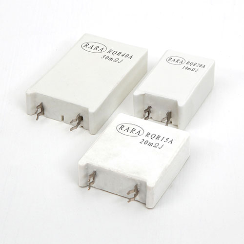 |
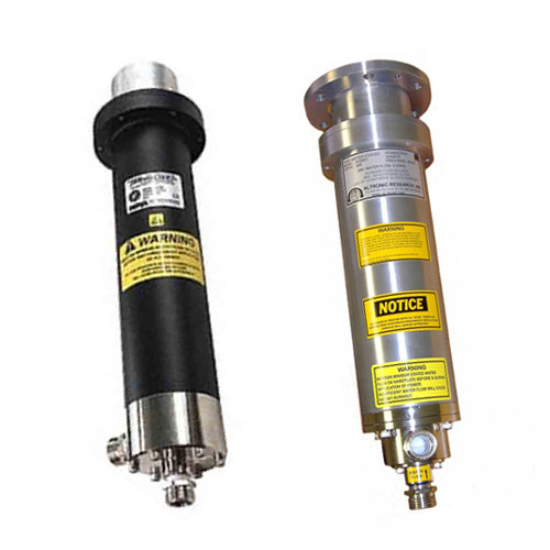 |
|
|
|
|
|
|
|
|
|
|
|
|
|
|
|
|
| Invented in 1962 by Felix Zandman. |
| Invented in 1962 by Felix Zandman. |
| Invented in 1962 by Felix Zandman. |
| Invented in 1962 by Felix Zandman. |
| Invented in 1962 by Felix Zandman. |
| Resistor, Thermistor |
| Resistor, Thermistor |
| Resistor, Thermistor |
| Resistor, Thermistor |
| Resistor, Thermistor |
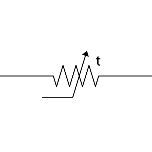 |
|
|
|
|
| Definition: A resistor made of semiconductor material having resistance that varies rapidly and predictably with temperature. Used as a temperature sensor, the resistance varies inversely with temperature. |
| Definition: A resistor made of semiconductor material having resistance that varies rapidly and predictably with temperature. Used as a temperature sensor, the resistance varies inversely with temperature. |
| Definition: A resistor made of semiconductor material having resistance that varies rapidly and predictably with temperature. Used as a temperature sensor, the resistance varies inversely with temperature. |
| Definition: A resistor made of semiconductor material having resistance that varies rapidly and predictably with temperature. Used as a temperature sensor, the resistance varies inversely with temperature. |
| Definition: A resistor made of semiconductor material having resistance that varies rapidly and predictably with temperature. Used as a temperature sensor, the resistance varies inversely with temperature. |
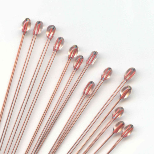 |
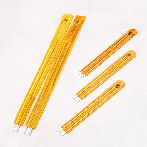 |
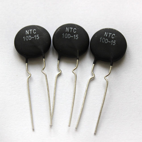 |
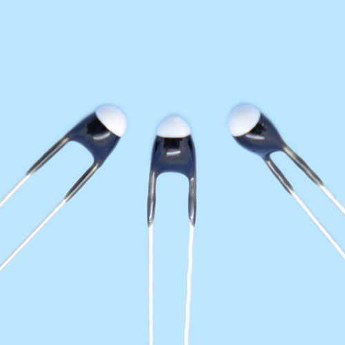 |
|
|
|
|
|
|
|
|
|
|
|
|
|
|
|
|
| Invented in 1833 by Michael Faraday. |
| Invented in 1833 by Michael Faraday. |
| Invented in 1833 by Michael Faraday. |
| Invented in 1833 by Michael Faraday. |
| Invented in 1833 by Michael Faraday. |
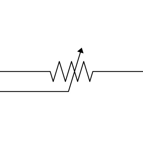 |
|
|
|
|
| Definition: This is a two or three terminal resistor that is generally used to control current and to vary the resistance in a circuit without interruption. The construction is very similar to a potentiometer, however rheostats will always use two connections, even if three terminals are present with one connection made to one end of the element and the other to the central wiper connection. As rheostats carry significant currents, wire wound resistors surround an insulating ceramic core allowing the wiper to slide over the windings. Rheostats are rarely used, as low voltage circuit design can achieve the same with safer, more efficient, methods of control. |
| Definition: This is a two or three terminal resistor that is generally used to control current and to vary the resistance in a circuit without interruption. The construction is very similar to a potentiometer, however rheostats will always use two connections, even if three terminals are present with one connection made to one end of the element and the other to the central wiper connection. As rheostats carry significant currents, wire wound resistors surround an insulating ceramic core allowing the wiper to slide over the windings. Rheostats are rarely used, as low voltage circuit design can achieve the same with safer, more efficient, methods of control. |
| Definition: This is a two or three terminal resistor that is generally used to control current and to vary the resistance in a circuit without interruption. The construction is very similar to a potentiometer, however rheostats will always use two connections, even if three terminals are present with one connection made to one end of the element and the other to the central wiper connection. As rheostats carry significant currents, wire wound resistors surround an insulating ceramic core allowing the wiper to slide over the windings. Rheostats are rarely used, as low voltage circuit design can achieve the same with safer, more efficient, methods of control. |
| Definition: This is a two or three terminal resistor that is generally used to control current and to vary the resistance in a circuit without interruption. The construction is very similar to a potentiometer, however rheostats will always use two connections, even if three terminals are present with one connection made to one end of the element and the other to the central wiper connection. As rheostats carry significant currents, wire wound resistors surround an insulating ceramic core allowing the wiper to slide over the windings. Rheostats are rarely used, as low voltage circuit design can achieve the same with safer, more efficient, methods of control. |
| Definition: This is a two or three terminal resistor that is generally used to control current and to vary the resistance in a circuit without interruption. The construction is very similar to a potentiometer, however rheostats will always use two connections, even if three terminals are present with one connection made to one end of the element and the other to the central wiper connection. As rheostats carry significant currents, wire wound resistors surround an insulating ceramic core allowing the wiper to slide over the windings. Rheostats are rarely used, as low voltage circuit design can achieve the same with safer, more efficient, methods of control. |
| Rheostat |
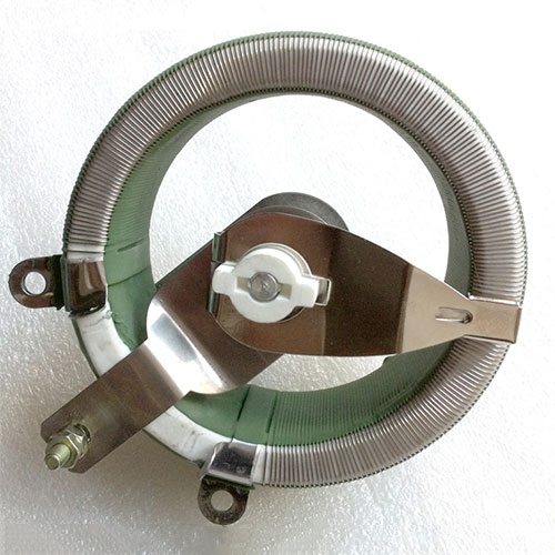 |
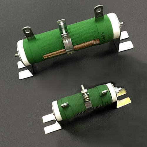 |
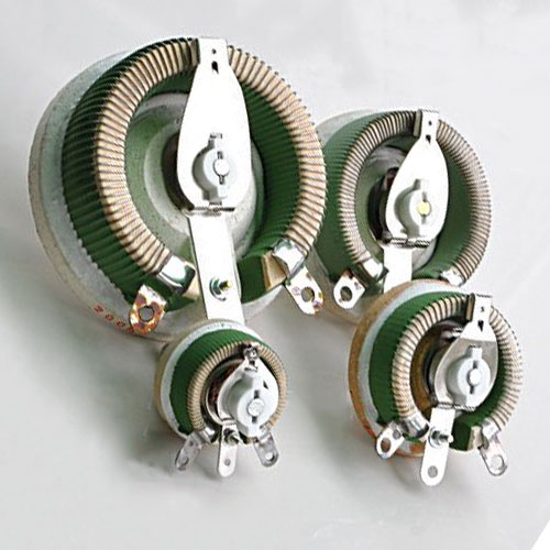 |
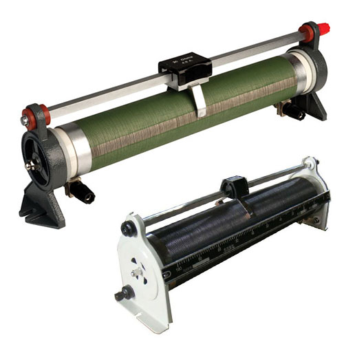 |
| Rheostat |
|
|
|
|
| Rheostat |
|
|
|
|
| Rheostat |
|
|
|
|
| Rheostat |
|
|
|
|
| Invented in 1872 by Thomas Alva Edison. |
| Invented in 1872 by Thomas Alva Edison. |
| Invented in 1872 by Thomas Alva Edison. |
| Invented in 1872 by Thomas Alva Edison. |
| Invented in 1872 by Thomas Alva Edison. |
| Potentiometer |
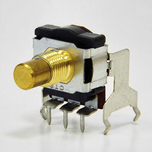 |
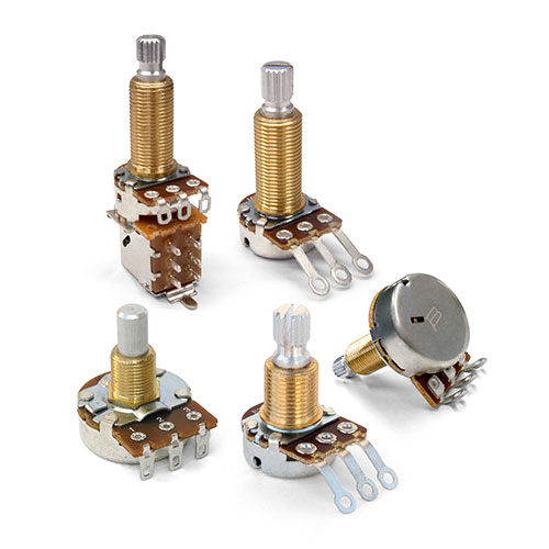 |
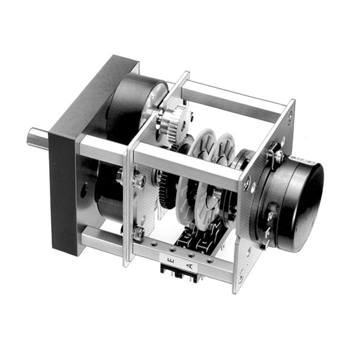 |
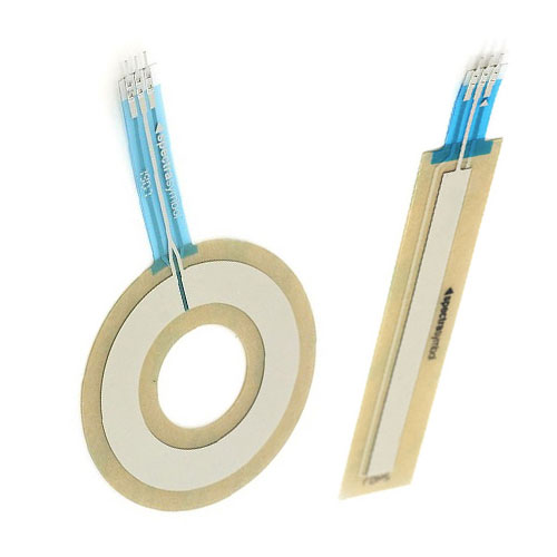 |
| Potentiometer |
|
|
|
|
| Potentiometer |
|
|
|
|
| Potentiometer |
|
|
|
|
| Potentiometer |
|
|
|
|
| Definition: This is a two or three terminal resistor with a digital, sliding or rotating contact for use as an adjustable voltage divider. If only two terminals are used, with the wiper, it will act as a variable resistor or rheostat, with direct control of less than one watt. |
| Definition: This is a two or three terminal resistor with a digital, sliding or rotating contact for use as an adjustable voltage divider. If only two terminals are used, with the wiper, it will act as a variable resistor or rheostat, with direct control of less than one watt. |
| Definition: This is a two or three terminal resistor with a digital, sliding or rotating contact for use as an adjustable voltage divider. If only two terminals are used, with the wiper, it will act as a variable resistor or rheostat, with direct control of less than one watt. |
| Definition: This is a two or three terminal resistor with a digital, sliding or rotating contact for use as an adjustable voltage divider. If only two terminals are used, with the wiper, it will act as a variable resistor or rheostat, with direct control of less than one watt. |
| Definition: This is a two or three terminal resistor with a digital, sliding or rotating contact for use as an adjustable voltage divider. If only two terminals are used, with the wiper, it will act as a variable resistor or rheostat, with direct control of less than one watt. |
| Invented in 1833 by Samuel Hunter Christie. |
| Invented in 1833 by Samuel Hunter Christie. |
| Invented in 1833 by Samuel Hunter Christie. |
| Invented in 1833 by Samuel Hunter Christie. |
| Invented in 1833 by Samuel Hunter Christie. |
| Trimpot |
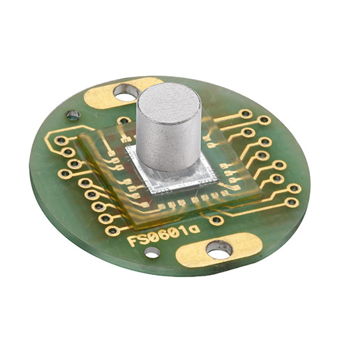 |
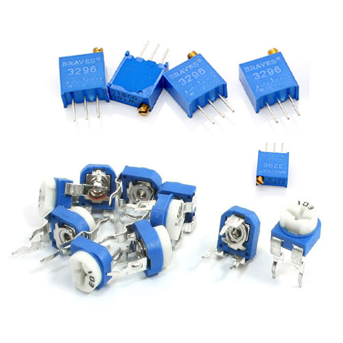 |
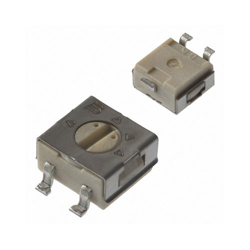 |
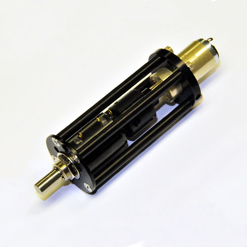 |
| Trimpot |
|
|
|
|
| Trimpot |
|
|
|
|
| Trimpot |
|
|
|
|
| Trimpot |
|
|
|
|
| Definition: Commonly known as trimmers, presets or trimpots, these miniature adjustable potentiometers are used for initial calibration, service, or to adjust set points or values of which the end user will never see or adjust. Trimpots are mounted directly on circuit boards and are turned with a small plastic screwdriver to avoid induction or conductance affecting calibration. Available in single or multi turn, for greater precision. |
| Definition: Commonly known as trimmers, presets or trimpots, these miniature adjustable potentiometers are used for initial calibration, service, or to adjust set points or values of which the end user will never see or adjust. Trimpots are mounted directly on circuit boards and are turned with a small plastic screwdriver to avoid induction or conductance affecting calibration. Available in single or multi turn, for greater precision. |
| Definition: Commonly known as trimmers, presets or trimpots, these miniature adjustable potentiometers are used for initial calibration, service, or to adjust set points or values of which the end user will never see or adjust. Trimpots are mounted directly on circuit boards and are turned with a small plastic screwdriver to avoid induction or conductance affecting calibration. Available in single or multi turn, for greater precision. |
| Definition: Commonly known as trimmers, presets or trimpots, these miniature adjustable potentiometers are used for initial calibration, service, or to adjust set points or values of which the end user will never see or adjust. Trimpots are mounted directly on circuit boards and are turned with a small plastic screwdriver to avoid induction or conductance affecting calibration. Available in single or multi turn, for greater precision. |
| Definition: Commonly known as trimmers, presets or trimpots, these miniature adjustable potentiometers are used for initial calibration, service, or to adjust set points or values of which the end user will never see or adjust. Trimpots are mounted directly on circuit boards and are turned with a small plastic screwdriver to avoid induction or conductance affecting calibration. Available in single or multi turn, for greater precision. |
| Invented in 1952 by Marlan Bourns. |
| Invented in 1952 by Marlan Bourns. |
| Invented in 1952 by Marlan Bourns. |
| Invented in 1952 by Marlan Bourns. |
| Invented in 1952 by Marlan Bourns. |
| CAPACITORS · INDUCTORS · TRANSFORMERS MEMRISTORS · RESISTORS · IDENTITY |
| CAPACITORS · INDUCTORS · TRANSFORMERS MEMRISTORS · RESISTORS · IDENTITY |
| CAPACITORS · INDUCTORS · TRANSFORMERS MEMRISTORS · RESISTORS · IDENTITY |
| CAPACITORS · INDUCTORS · TRANSFORMERS MEMRISTORS · RESISTORS · IDENTITY |
| CAPACITORS · INDUCTORS · TRANSFORMERS MEMRISTORS · RESISTORS · IDENTITY |
| Resistors Colour Code |
| Resistors Colour Code |
| Resistors Colour Code |
| Resistors Colour Code |
| Resistors Colour Code |
| 4 Band | 5 Band | 6 Band, Tolerance & Temperature Coefficient |
| 4 Band | 5 Band | 6 Band, Tolerance & Temperature Coefficient |
| 4 Band | 5 Band | 6 Band, Tolerance & Temperature Coefficient |
| 4 Band | 5 Band | 6 Band, Tolerance & Temperature Coefficient |
| 4 Band | 5 Band | 6 Band, Tolerance & Temperature Coefficient |

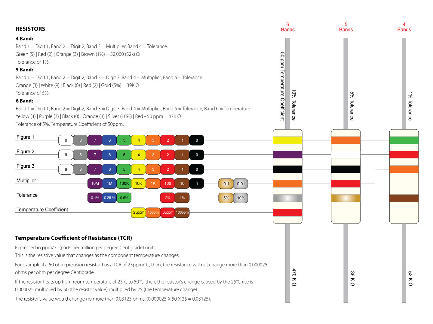