INTELLECTUM VIRTUS
INTELLECTUM VIRTUS
INTELLECTUM VIRTUS
INTELLECTUM VIRTUS
INTELLECTUM VIRTUS
ELECTRICAL ENGINEERING
ELECTRICAL ENGINEERING
ELECTRICAL ENGINEERING
ELECTRICAL ENGINEERING
ELECTRICAL ENGINEERING
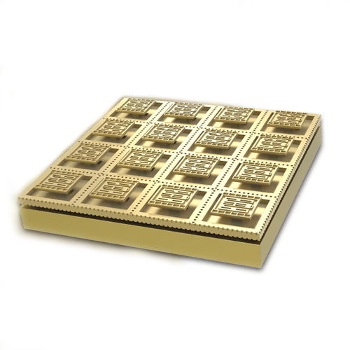
ACTIVE COMPONENT REGISTER
ACTIVE COMPONENT REGISTER
ACTIVE COMPONENT REGISTER
ACTIVE COMPONENT REGISTER
ACTIVE COMPONENT REGISTER
Audio, Communication, Computer
Conduction, Control, Display, Illumination
Motion, Power & Temperature
Audio, Communication, Computer
Conduction, Control, Display, Illumination
Motion, Power & Temperature
Audio, Communication, Computer
Conduction, Control, Display, Illumination
Motion, Power & Temperature
Audio, Communication, Computer
Conduction, Control, Display, Illumination
Motion, Power & Temperature
Audio, Communication, Computer
Conduction, Control, Display, Illumination
Motion, Power & Temperature
| AUDIO · COMMUNICATION · COMPUTER CONDUCTION · CONTROL · DISPLAY · ILLUMINATION MOTION · POWER · TEMPERATURE · IDENTITY |
| AUDIO · COMMUNICATION · COMPUTER CONDUCTION · CONTROL · DISPLAY · ILLUMINATION MOTION · POWER · TEMPERATURE · IDENTITY |
| AUDIO · COMMUNICATION · COMPUTER CONDUCTION · CONTROL · DISPLAY · ILLUMINATION MOTION · POWER · TEMPERATURE · IDENTITY |
| AUDIO · COMMUNICATION · COMPUTER CONDUCTION · CONTROL · DISPLAY · ILLUMINATION MOTION · POWER · TEMPERATURE · IDENTITY |
| AUDIO · COMMUNICATION · COMPUTER CONDUCTION · CONTROL · DISPLAY · ILLUMINATION MOTION · POWER · TEMPERATURE · IDENTITY |
 |
|
|
|
|
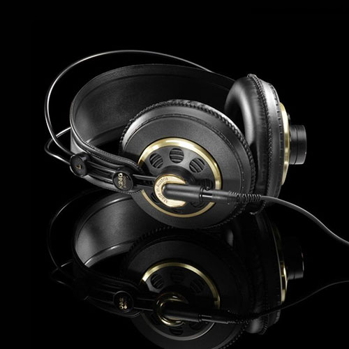
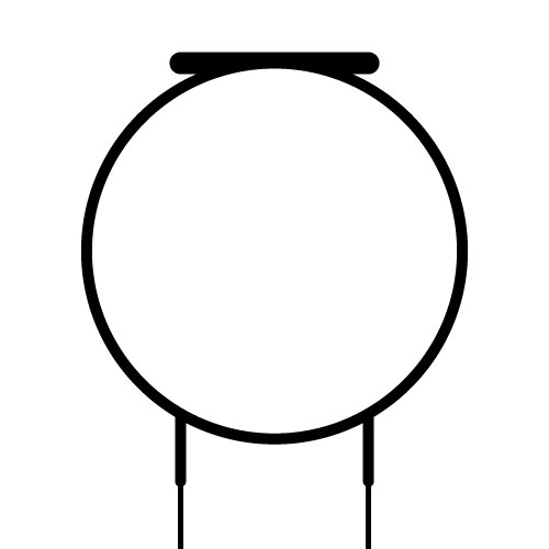
| Definition: Headphones are electro-acoustic transducers, which convert electrical signals to their corresponding audio sounds to the ears of the user with low power consumption. Used originally by radio pioneers and also by radio telephone and telegraph operators allowing a better audio reception without disruption. |
| Definition: Headphones are electro-acoustic transducers, which convert electrical signals to their corresponding audio sounds to the ears of the user with low power consumption. Used originally by radio pioneers and also by radio telephone and telegraph operators allowing a better audio reception without disruption. |
| Definition: Headphones are electro-acoustic transducers, which convert electrical signals to their corresponding audio sounds to the ears of the user with low power consumption. Used originally by radio pioneers and also by radio telephone and telegraph operators allowing a better audio reception without disruption. |
| Definition: Headphones are electro-acoustic transducers, which convert electrical signals to their corresponding audio sounds to the ears of the user with low power consumption. Used originally by radio pioneers and also by radio telephone and telegraph operators allowing a better audio reception without disruption. |
| Definition: Headphones are electro-acoustic transducers, which convert electrical signals to their corresponding audio sounds to the ears of the user with low power consumption. Used originally by radio pioneers and also by radio telephone and telegraph operators allowing a better audio reception without disruption. |
 |
 |
 |
 |
|
|
|
|
|
|
|
|
|
|
|
|
|
|
|
|
| Invented in 1910 by Nathaniel Baldwin. |
| Invented in 1910 by Nathaniel Baldwin. |
| Invented in 1910 by Nathaniel Baldwin. |
| Invented in 1910 by Nathaniel Baldwin. |
| Invented in 1910 by Nathaniel Baldwin. |
 |
|
|
|
|
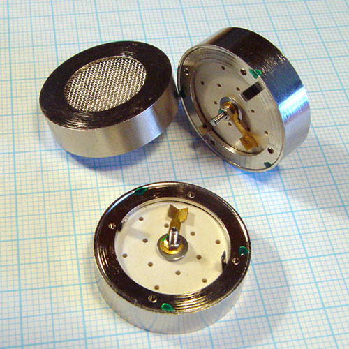
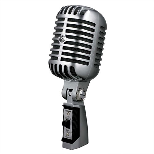
| Definition: Microphones are an acoustic-to-electric transducer which facilitate the conversion of acoustic signals into electrical signals. Those using electromagnetic induction are known as dynamic, capacitive based, a condenser and the piezoelectric type, based on changes in air pressure. |
| Definition: Microphones are an acoustic-to-electric transducer which facilitate the conversion of acoustic signals into electrical signals. Those using electromagnetic induction are known as dynamic, capacitive based, a condenser and the piezoelectric type, based on changes in air pressure. |
| Definition: Microphones are an acoustic-to-electric transducer which facilitate the conversion of acoustic signals into electrical signals. Those using electromagnetic induction are known as dynamic, capacitive based, a condenser and the piezoelectric type, based on changes in air pressure. |
| Definition: Microphones are an acoustic-to-electric transducer which facilitate the conversion of acoustic signals into electrical signals. Those using electromagnetic induction are known as dynamic, capacitive based, a condenser and the piezoelectric type, based on changes in air pressure. |
| Definition: Microphones are an acoustic-to-electric transducer which facilitate the conversion of acoustic signals into electrical signals. Those using electromagnetic induction are known as dynamic, capacitive based, a condenser and the piezoelectric type, based on changes in air pressure. |
 |
 |
 |
 |
|
|
|
|
|
|
|
|
|
|
|
|
|
|
|
|
| Invented in 1876 by Emile Berliner. |
| Invented in 1876 by Emile Berliner. |
| Invented in 1876 by Emile Berliner. |
| Invented in 1876 by Emile Berliner. |
| Invented in 1876 by Emile Berliner. |
 |
|
|
|
|
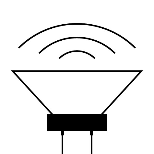
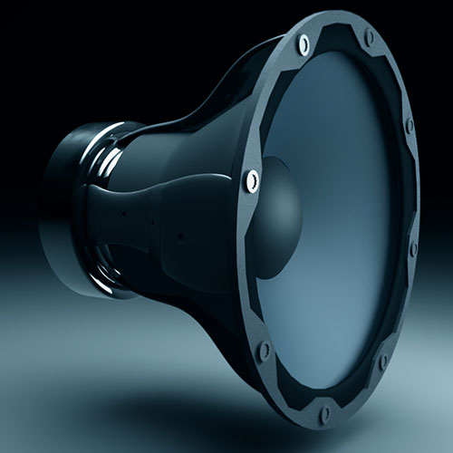
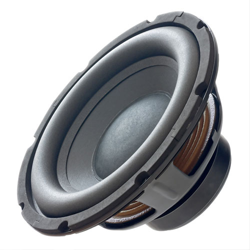
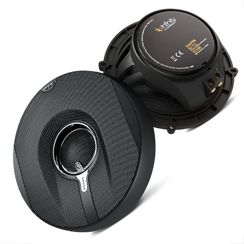
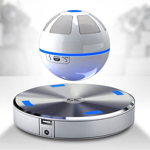
| Definition: Also known as a loudspeaker, this device can contain one or more electroacoustic transducers that convert electrical signals into their corresponding sounds. The first loudspeakers were for telephone systems in the late 1800s, and grew popular with the advent of amplification by vacuum tubes since 1912. The dynamic speaker, invented in 1925 operates on the same basic principle as a dynamic microphone, but in reverse, to produce sound from an electrical signal. When an alternating current electrical audio signal is applied to a coil of wire suspended in a circular gap between the poles of a permanent magnet, the coil is forced to move rapidly back and forth causing a diaphragm attached to the coil to move in sync which pushes air and creates sound waves. |
| Definition: Also known as a loudspeaker, this device can contain one or more electroacoustic transducers that convert electrical signals into their corresponding sounds. The first loudspeakers were for telephone systems in the late 1800s, and grew popular with the advent of amplification by vacuum tubes since 1912. The dynamic speaker, invented in 1925 operates on the same basic principle as a dynamic microphone, but in reverse, to produce sound from an electrical signal. When an alternating current electrical audio signal is applied to a coil of wire suspended in a circular gap between the poles of a permanent magnet, the coil is forced to move rapidly back and forth causing a diaphragm attached to the coil to move in sync which pushes air and creates sound waves. |
| Definition: Also known as a loudspeaker, this device can contain one or more electroacoustic transducers that convert electrical signals into their corresponding sounds. The first loudspeakers were for telephone systems in the late 1800s, and grew popular with the advent of amplification by vacuum tubes since 1912. The dynamic speaker, invented in 1925 operates on the same basic principle as a dynamic microphone, but in reverse, to produce sound from an electrical signal. When an alternating current electrical audio signal is applied to a coil of wire suspended in a circular gap between the poles of a permanent magnet, the coil is forced to move rapidly back and forth causing a diaphragm attached to the coil to move in sync which pushes air and creates sound waves. |
| Definition: Also known as a loudspeaker, this device can contain one or more electroacoustic transducers that convert electrical signals into their corresponding sounds. The first loudspeakers were for telephone systems in the late 1800s, and grew popular with the advent of amplification by vacuum tubes since 1912. The dynamic speaker, invented in 1925 operates on the same basic principle as a dynamic microphone, but in reverse, to produce sound from an electrical signal. When an alternating current electrical audio signal is applied to a coil of wire suspended in a circular gap between the poles of a permanent magnet, the coil is forced to move rapidly back and forth causing a diaphragm attached to the coil to move in sync which pushes air and creates sound waves. |
| Definition: Also known as a loudspeaker, this device can contain one or more electroacoustic transducers that convert electrical signals into their corresponding sounds. The first loudspeakers were for telephone systems in the late 1800s, and grew popular with the advent of amplification by vacuum tubes since 1912. The dynamic speaker, invented in 1925 operates on the same basic principle as a dynamic microphone, but in reverse, to produce sound from an electrical signal. When an alternating current electrical audio signal is applied to a coil of wire suspended in a circular gap between the poles of a permanent magnet, the coil is forced to move rapidly back and forth causing a diaphragm attached to the coil to move in sync which pushes air and creates sound waves. |
 |
 |
 |
 |
|
|
|
|
|
|
|
|
|
|
|
|
|
|
|
|
| Invented in 1874 by Ernst Werner von Siemens. |
| Invented in 1874 by Ernst Werner von Siemens. |
| Invented in 1874 by Ernst Werner von Siemens. |
| Invented in 1874 by Ernst Werner von Siemens. |
| Invented in 1874 by Ernst Werner von Siemens. |
| AUDIO · COMMUNICATION · COMPUTER CONDUCTION · CONTROL · DISPLAY · ILLUMINATION MOTION · POWER · TEMPERATURE · IDENTITY |
| AUDIO · COMMUNICATION · COMPUTER CONDUCTION · CONTROL · DISPLAY · ILLUMINATION MOTION · POWER · TEMPERATURE · IDENTITY |
| AUDIO · COMMUNICATION · COMPUTER CONDUCTION · CONTROL · DISPLAY · ILLUMINATION MOTION · POWER · TEMPERATURE · IDENTITY |
| AUDIO · COMMUNICATION · COMPUTER CONDUCTION · CONTROL · DISPLAY · ILLUMINATION MOTION · POWER · TEMPERATURE · IDENTITY |
| AUDIO · COMMUNICATION · COMPUTER CONDUCTION · CONTROL · DISPLAY · ILLUMINATION MOTION · POWER · TEMPERATURE · IDENTITY |
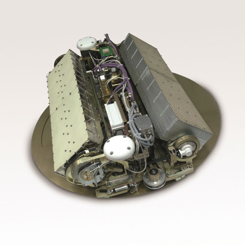
| Antenna Phased Array |
| Antenna Phased Array |
| Antenna Phased Array |
| Antenna Phased Array |
| Antenna Phased Array |
 |
|
|
|
|
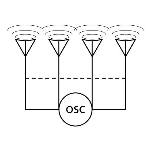
| Definition: A phased array is an antenna group in which relative phases of respective signals feed the antennas, building a radiation pattern to directionally reinforce signal strength. The phase relationships among the antennas may be fixed, as in a tower array, or adjustable, for beam steering. Over 100 years later, the MESSENGER spacecraft, the space probe mission to the planet Mercury (2011–2015), was the first deep-space mission to use a phased-array antenna for communications. |
| Definition: A phased array is an antenna group in which relative phases of respective signals feed the antennas, building a radiation pattern to directionally reinforce signal strength. The phase relationships among the antennas may be fixed, as in a tower array, or adjustable, for beam steering. Over 100 years later, the MESSENGER spacecraft, the space probe mission to the planet Mercury (2011–2015), was the first deep-space mission to use a phased-array antenna for communications. |
| Definition: A phased array is an antenna group in which relative phases of respective signals feed the antennas, building a radiation pattern to directionally reinforce signal strength. The phase relationships among the antennas may be fixed, as in a tower array, or adjustable, for beam steering. Over 100 years later, the MESSENGER spacecraft, the space probe mission to the planet Mercury (2011–2015), was the first deep-space mission to use a phased-array antenna for communications. |
| Definition: A phased array is an antenna group in which relative phases of respective signals feed the antennas, building a radiation pattern to directionally reinforce signal strength. The phase relationships among the antennas may be fixed, as in a tower array, or adjustable, for beam steering. Over 100 years later, the MESSENGER spacecraft, the space probe mission to the planet Mercury (2011–2015), was the first deep-space mission to use a phased-array antenna for communications. |
| Definition: A phased array is an antenna group in which relative phases of respective signals feed the antennas, building a radiation pattern to directionally reinforce signal strength. The phase relationships among the antennas may be fixed, as in a tower array, or adjustable, for beam steering. Over 100 years later, the MESSENGER spacecraft, the space probe mission to the planet Mercury (2011–2015), was the first deep-space mission to use a phased-array antenna for communications. |
 |
 |
 |
 |
|
|
|
|
|
|
|
|
|
|
|
|
|
|
|
|
| Invented in 1905 by Karl Ferdinand Braun. |
| Invented in 1905 by Karl Ferdinand Braun. |
| Invented in 1905 by Karl Ferdinand Braun. |
| Invented in 1905 by Karl Ferdinand Braun. |
| Invented in 1905 by Karl Ferdinand Braun. |
| AUDIO · COMMUNICATION · COMPUTER CONDUCTION · CONTROL · DISPLAY · ILLUMINATION MOTION · POWER · TEMPERATURE · IDENTITY |
| AUDIO · COMMUNICATION · COMPUTER CONDUCTION · CONTROL · DISPLAY · ILLUMINATION MOTION · POWER · TEMPERATURE · IDENTITY |
| AUDIO · COMMUNICATION · COMPUTER CONDUCTION · CONTROL · DISPLAY · ILLUMINATION MOTION · POWER · TEMPERATURE · IDENTITY |
| AUDIO · COMMUNICATION · COMPUTER CONDUCTION · CONTROL · DISPLAY · ILLUMINATION MOTION · POWER · TEMPERATURE · IDENTITY |
| AUDIO · COMMUNICATION · COMPUTER CONDUCTION · CONTROL · DISPLAY · ILLUMINATION MOTION · POWER · TEMPERATURE · IDENTITY |
 |
|
|
|
|
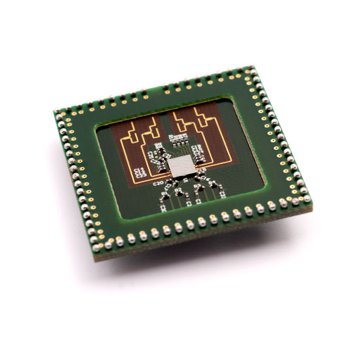
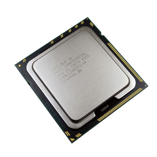
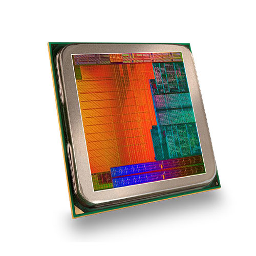
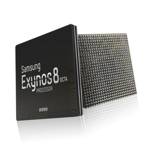
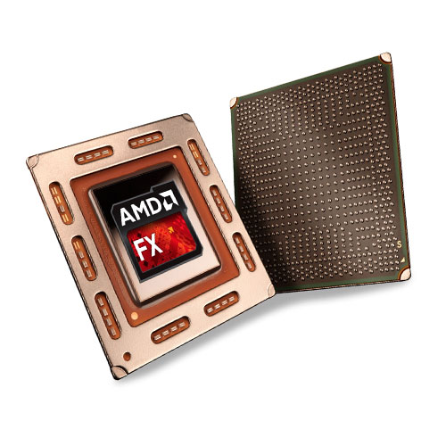
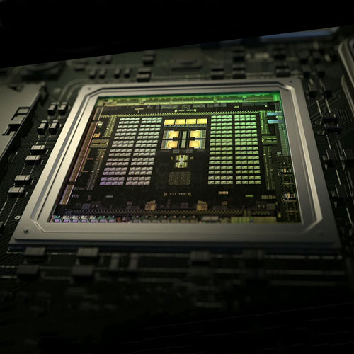
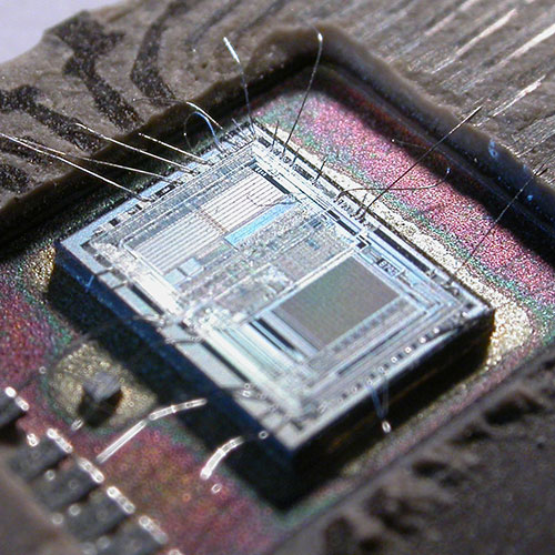
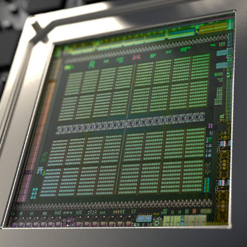
| Definition: Central Processing Unit, CPU, is the main integrated circuit within a computer that carries out instructions via an interactive computer program and the role of this microprocessor is to perform basic arithmetic, logical, control and input/output (I/O) operations. In a multi-core processor, a single chip will contain more than one CPU and are known as cores. |
| Definition: Central Processing Unit, CPU, is the main integrated circuit within a computer that carries out instructions via an interactive computer program and the role of this microprocessor is to perform basic arithmetic, logical, control and input/output (I/O) operations. In a multi-core processor, a single chip will contain more than one CPU and are known as cores. |
| Definition: Central Processing Unit, CPU, is the main integrated circuit within a computer that carries out instructions via an interactive computer program and the role of this microprocessor is to perform basic arithmetic, logical, control and input/output (I/O) operations. In a multi-core processor, a single chip will contain more than one CPU and are known as cores. |
| Definition: Central Processing Unit, CPU, is the main integrated circuit within a computer that carries out instructions via an interactive computer program and the role of this microprocessor is to perform basic arithmetic, logical, control and input/output (I/O) operations. In a multi-core processor, a single chip will contain more than one CPU and are known as cores. |
| Definition: Central Processing Unit, CPU, is the main integrated circuit within a computer that carries out instructions via an interactive computer program and the role of this microprocessor is to perform basic arithmetic, logical, control and input/output (I/O) operations. In a multi-core processor, a single chip will contain more than one CPU and are known as cores. |
 |
 |
 |
 |
|
|
|
|
|
|
|
|
|
|
|
|
|
|
|
|
| Invented in 1945 by John von Neumann. |
| Invented in 1945 by John von Neumann. |
| Invented in 1945 by John von Neumann. |
| Invented in 1945 by John von Neumann. |
| Invented in 1945 by John von Neumann. |
 |
|
|
|
|
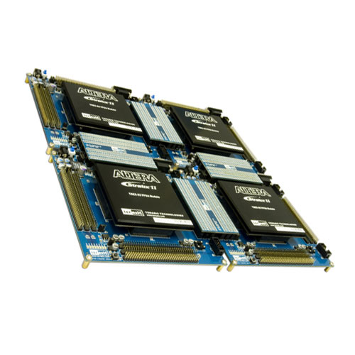
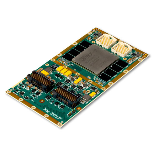
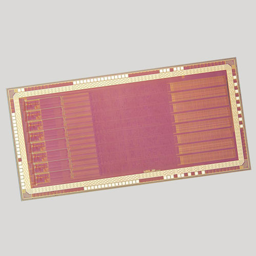
| Definition: Field Programmable Gate Array, FPGA, belongs to a family of general-purpose logic devices that can be configured dynamically via a programming interface to perform complex logic functions and is often used for prototyping production IC devices. They contain an array of programmable logic blocks with a hierarchy of reconfigurable interconnects and allow the blocks to be “wired together”. Logic blocks can be configured to perform complex combinational functions, or merely simple logic gates to flip-flops. |
| Definition: Field Programmable Gate Array, FPGA, belongs to a family of general-purpose logic devices that can be configured dynamically via a programming interface to perform complex logic functions and is often used for prototyping production IC devices. They contain an array of programmable logic blocks with a hierarchy of reconfigurable interconnects and allow the blocks to be “wired together”. Logic blocks can be configured to perform complex combinational functions, or merely simple logic gates to flip-flops. |
| Definition: Field Programmable Gate Array, FPGA, belongs to a family of general-purpose logic devices that can be configured dynamically via a programming interface to perform complex logic functions and is often used for prototyping production IC devices. They contain an array of programmable logic blocks with a hierarchy of reconfigurable interconnects and allow the blocks to be “wired together”. Logic blocks can be configured to perform complex combinational functions, or merely simple logic gates to flip-flops. |
| Definition: Field Programmable Gate Array, FPGA, belongs to a family of general-purpose logic devices that can be configured dynamically via a programming interface to perform complex logic functions and is often used for prototyping production IC devices. They contain an array of programmable logic blocks with a hierarchy of reconfigurable interconnects and allow the blocks to be “wired together”. Logic blocks can be configured to perform complex combinational functions, or merely simple logic gates to flip-flops. |
| Definition: Field Programmable Gate Array, FPGA, belongs to a family of general-purpose logic devices that can be configured dynamically via a programming interface to perform complex logic functions and is often used for prototyping production IC devices. They contain an array of programmable logic blocks with a hierarchy of reconfigurable interconnects and allow the blocks to be “wired together”. Logic blocks can be configured to perform complex combinational functions, or merely simple logic gates to flip-flops. |
 |
 |
 |
 |
|
|
|
|
|
|
|
|
|
|
|
|
|
|
|
|
| Invented in 1992 by Steve Casselman. |
| Invented in 1992 by Steve Casselman. |
| Invented in 1992 by Steve Casselman. |
| Invented in 1992 by Steve Casselman. |
| Invented in 1992 by Steve Casselman. |
| Definition: There are two main types of memory, “volatile memory” only retains data while the device is powered and “no-volatile” which stores the data. Memory capacity is specified in bytes and with interval powers of 1,000, beginning with the Kilo k – Thousand, Mega M – Million, Giga G – Billion, Tera T – Trillion, Peta P – Quadrillion, Exa E – Quintillion, Zetta Z – Sextillion and Yotta Y – Septillion. There are five main divisions of memory storage: “Cache” memory (volatile memory) maximises interface speed of Processor Registers and Cache by reducing reading from or writing to main memory and multiplexing tasks to a group of optimised, high speed (content addressable) cache memory, from an instruction cache, to a data cache with translation buffer for virtual-to-physical address translation, whereby the memory management unit (MMU), prioritises processor tasks and manages the cache throughput to the “Primary Storage” memory. Static Random Access Memory (SRAM) have six transistors and form a digital flip-flop circuit for each bit. They are faster than their DRAM counterpart and do not require additional circuitry to maintain their logical state. “Primary Storage” (volatile memory), is addressable Random Access Memory (RAM) which is used to store information for immediate use, as power is required to maintain their stored information. Examples are: SDRAM of DDR, DDR2, DDR3, DDR4 and DDR5; 1T RAM, MCDRAM, MDRAM; RDRAM; PSRAM and 3D HCM. “Secondary Storage” (non-volatile memory), transfers data, with the aid of “virtual memory”, to store, without power, large amounts of information. Examples are: Paper Tape, Punched Card, Flash, ROM, PROM, EPROM, EEPROM, Magnetic Tape, Optical Drive, Floppy Disk Drive, Hard Disk Drive and Solid State Drive. “Tertiary Storage” (non-volatile memory), employs offline storage with network and cloud based systems. “Video Storage” (volatile memory), is addressable dual ported video Random Access Memory (VRAM) with its own cache subsystem and is used to store and buffer, image data between the computer display and the computer processor. The first, DRAM port, is accessed by the processor in the same manner as primary storage memory, whilst the second, video port, is dedicated to providing a high throughput, serialised data channel for the graphic chipset. Modern memory is SGRAM of GDDR to GDDR5 and 3D HBM. |
| Definition: There are two main types of memory, “volatile memory” only retains data while the device is powered and “no-volatile” which stores the data. Memory capacity is specified in bytes and with interval powers of 1,000, beginning with the Kilo k – Thousand, Mega M – Million, Giga G – Billion, Tera T – Trillion, Peta P – Quadrillion, Exa E – Quintillion, Zetta Z – Sextillion and Yotta Y – Septillion. There are five main divisions of memory storage: “Cache” memory (volatile memory) maximises interface speed of Processor Registers and Cache by reducing reading from or writing to main memory and multiplexing tasks to a group of optimised, high speed (content addressable) cache memory, from an instruction cache, to a data cache with translation buffer for virtual-to-physical address translation, whereby the memory management unit (MMU), prioritises processor tasks and manages the cache throughput to the “Primary Storage” memory. Static Random Access Memory (SRAM) have six transistors and form a digital flip-flop circuit for each bit. They are faster than their DRAM counterpart and do not require additional circuitry to maintain their logical state. “Primary Storage” (volatile memory), is addressable Random Access Memory (RAM) which is used to store information for immediate use, as power is required to maintain their stored information. Examples are: SDRAM of DDR, DDR2, DDR3, DDR4 and DDR5; 1T RAM, MCDRAM, MDRAM; RDRAM; PSRAM and 3D HCM. “Secondary Storage” (non-volatile memory), transfers data, with the aid of “virtual memory”, to store, without power, large amounts of information. Examples are: Paper Tape, Punched Card, Flash, ROM, PROM, EPROM, EEPROM, Magnetic Tape, Optical Drive, Floppy Disk Drive, Hard Disk Drive and Solid State Drive. “Tertiary Storage” (non-volatile memory), employs offline storage with network and cloud based systems. “Video Storage” (volatile memory), is addressable dual ported video Random Access Memory (VRAM) with its own cache subsystem and is used to store and buffer, image data between the computer display and the computer processor. The first, DRAM port, is accessed by the processor in the same manner as primary storage memory, whilst the second, video port, is dedicated to providing a high throughput, serialised data channel for the graphic chipset. Modern memory is SGRAM of GDDR to GDDR5 and 3D HBM. |
| Definition: There are two main types of memory, “volatile memory” only retains data while the device is powered and “no-volatile” which stores the data. Memory capacity is specified in bytes and with interval powers of 1,000, beginning with the Kilo k – Thousand, Mega M – Million, Giga G – Billion, Tera T – Trillion, Peta P – Quadrillion, Exa E – Quintillion, Zetta Z – Sextillion and Yotta Y – Septillion. There are five main divisions of memory storage: “Cache” memory (volatile memory) maximises interface speed of Processor Registers and Cache by reducing reading from or writing to main memory and multiplexing tasks to a group of optimised, high speed (content addressable) cache memory, from an instruction cache, to a data cache with translation buffer for virtual-to-physical address translation, whereby the memory management unit (MMU), prioritises processor tasks and manages the cache throughput to the “Primary Storage” memory. Static Random Access Memory (SRAM) have six transistors and form a digital flip-flop circuit for each bit. They are faster than their DRAM counterpart and do not require additional circuitry to maintain their logical state. “Primary Storage” (volatile memory), is addressable Random Access Memory (RAM) which is used to store information for immediate use, as power is required to maintain their stored information. Examples are: SDRAM of DDR, DDR2, DDR3, DDR4 and DDR5; 1T RAM, MCDRAM, MDRAM; RDRAM; PSRAM and 3D HCM. “Secondary Storage” (non-volatile memory), transfers data, with the aid of “virtual memory”, to store, without power, large amounts of information. Examples are: Paper Tape, Punched Card, Flash, ROM, PROM, EPROM, EEPROM, Magnetic Tape, Optical Drive, Floppy Disk Drive, Hard Disk Drive and Solid State Drive. “Tertiary Storage” (non-volatile memory), employs offline storage with network and cloud based systems. “Video Storage” (volatile memory), is addressable dual ported video Random Access Memory (VRAM) with its own cache subsystem and is used to store and buffer, image data between the computer display and the computer processor. The first, DRAM port, is accessed by the processor in the same manner as primary storage memory, whilst the second, video port, is dedicated to providing a high throughput, serialised data channel for the graphic chipset. Modern memory is SGRAM of GDDR to GDDR5 and 3D HBM. |
| Definition: There are two main types of memory, “volatile memory” only retains data while the device is powered and “no-volatile” which stores the data. Memory capacity is specified in bytes and with interval powers of 1,000, beginning with the Kilo k – Thousand, Mega M – Million, Giga G – Billion, Tera T – Trillion, Peta P – Quadrillion, Exa E – Quintillion, Zetta Z – Sextillion and Yotta Y – Septillion. There are five main divisions of memory storage: “Cache” memory (volatile memory) maximises interface speed of Processor Registers and Cache by reducing reading from or writing to main memory and multiplexing tasks to a group of optimised, high speed (content addressable) cache memory, from an instruction cache, to a data cache with translation buffer for virtual-to-physical address translation, whereby the memory management unit (MMU), prioritises processor tasks and manages the cache throughput to the “Primary Storage” memory. Static Random Access Memory (SRAM) have six transistors and form a digital flip-flop circuit for each bit. They are faster than their DRAM counterpart and do not require additional circuitry to maintain their logical state. “Primary Storage” (volatile memory), is addressable Random Access Memory (RAM) which is used to store information for immediate use, as power is required to maintain their stored information. Examples are: SDRAM of DDR, DDR2, DDR3, DDR4 and DDR5; 1T RAM, MCDRAM, MDRAM; RDRAM; PSRAM and 3D HCM. “Secondary Storage” (non-volatile memory), transfers data, with the aid of “virtual memory”, to store, without power, large amounts of information. Examples are: Paper Tape, Punched Card, Flash, ROM, PROM, EPROM, EEPROM, Magnetic Tape, Optical Drive, Floppy Disk Drive, Hard Disk Drive and Solid State Drive. “Tertiary Storage” (non-volatile memory), employs offline storage with network and cloud based systems. “Video Storage” (volatile memory), is addressable dual ported video Random Access Memory (VRAM) with its own cache subsystem and is used to store and buffer, image data between the computer display and the computer processor. The first, DRAM port, is accessed by the processor in the same manner as primary storage memory, whilst the second, video port, is dedicated to providing a high throughput, serialised data channel for the graphic chipset. Modern memory is SGRAM of GDDR to GDDR5 and 3D HBM. |
| Definition: There are two main types of memory, “volatile memory” only retains data while the device is powered and “no-volatile” which stores the data. Memory capacity is specified in bytes and with interval powers of 1,000, beginning with the Kilo k – Thousand, Mega M – Million, Giga G – Billion, Tera T – Trillion, Peta P – Quadrillion, Exa E – Quintillion, Zetta Z – Sextillion and Yotta Y – Septillion. There are five main divisions of memory storage: “Cache” memory (volatile memory) maximises interface speed of Processor Registers and Cache by reducing reading from or writing to main memory and multiplexing tasks to a group of optimised, high speed (content addressable) cache memory, from an instruction cache, to a data cache with translation buffer for virtual-to-physical address translation, whereby the memory management unit (MMU), prioritises processor tasks and manages the cache throughput to the “Primary Storage” memory. Static Random Access Memory (SRAM) have six transistors and form a digital flip-flop circuit for each bit. They are faster than their DRAM counterpart and do not require additional circuitry to maintain their logical state. “Primary Storage” (volatile memory), is addressable Random Access Memory (RAM) which is used to store information for immediate use, as power is required to maintain their stored information. Examples are: SDRAM of DDR, DDR2, DDR3, DDR4 and DDR5; 1T RAM, MCDRAM, MDRAM; RDRAM; PSRAM and 3D HCM. “Secondary Storage” (non-volatile memory), transfers data, with the aid of “virtual memory”, to store, without power, large amounts of information. Examples are: Paper Tape, Punched Card, Flash, ROM, PROM, EPROM, EEPROM, Magnetic Tape, Optical Drive, Floppy Disk Drive, Hard Disk Drive and Solid State Drive. “Tertiary Storage” (non-volatile memory), employs offline storage with network and cloud based systems. “Video Storage” (volatile memory), is addressable dual ported video Random Access Memory (VRAM) with its own cache subsystem and is used to store and buffer, image data between the computer display and the computer processor. The first, DRAM port, is accessed by the processor in the same manner as primary storage memory, whilst the second, video port, is dedicated to providing a high throughput, serialised data channel for the graphic chipset. Modern memory is SGRAM of GDDR to GDDR5 and 3D HBM. |
| Invented in 1946 by Sir Frederic Williams & Tom Kilburn. |
| Invented in 1946 by Sir Frederic Williams & Tom Kilburn. |
| Invented in 1946 by Sir Frederic Williams & Tom Kilburn. |
| Invented in 1946 by Sir Frederic Williams & Tom Kilburn. |
| Invented in 1946 by Sir Frederic Williams & Tom Kilburn. |
 |
|
|
|
|
| Definition: Known also as “CPU” or “Internal” memory, this is the random access memory (RAM) is preferably integrated directly within the CPU or placed before the RAM Modules with a priority bus interconnect with the CPU and allows for the microprocessor to access data faster than it can access the “Primary” RAM modules. The variations in design range from SRAM, eDRAM, STT-RAM, ReRAM, PCM and various 3-dimensional, multi-phase and multi-port designs. |
| Definition: Known also as “CPU” or “Internal” memory, this is the random access memory (RAM) is preferably integrated directly within the CPU or placed before the RAM Modules with a priority bus interconnect with the CPU and allows for the microprocessor to access data faster than it can access the “Primary” RAM modules. The variations in design range from SRAM, eDRAM, STT-RAM, ReRAM, PCM and various 3-dimensional, multi-phase and multi-port designs. |
| Definition: Known also as “CPU” or “Internal” memory, this is the random access memory (RAM) is preferably integrated directly within the CPU or placed before the RAM Modules with a priority bus interconnect with the CPU and allows for the microprocessor to access data faster than it can access the “Primary” RAM modules. The variations in design range from SRAM, eDRAM, STT-RAM, ReRAM, PCM and various 3-dimensional, multi-phase and multi-port designs. |
| Definition: Known also as “CPU” or “Internal” memory, this is the random access memory (RAM) is preferably integrated directly within the CPU or placed before the RAM Modules with a priority bus interconnect with the CPU and allows for the microprocessor to access data faster than it can access the “Primary” RAM modules. The variations in design range from SRAM, eDRAM, STT-RAM, ReRAM, PCM and various 3-dimensional, multi-phase and multi-port designs. |
| Definition: Known also as “CPU” or “Internal” memory, this is the random access memory (RAM) is preferably integrated directly within the CPU or placed before the RAM Modules with a priority bus interconnect with the CPU and allows for the microprocessor to access data faster than it can access the “Primary” RAM modules. The variations in design range from SRAM, eDRAM, STT-RAM, ReRAM, PCM and various 3-dimensional, multi-phase and multi-port designs. |
 |
 |
 |
 |
|
|
|
|
|
|
|
|
|
|
|
|
|
|
|
|
| Invented in 1965 by Sir Maurice Wilkes. |
| Invented in 1965 by Sir Maurice Wilkes. |
| Invented in 1965 by Sir Maurice Wilkes. |
| Invented in 1965 by Sir Maurice Wilkes. |
| Invented in 1965 by Sir Maurice Wilkes. |
 |
|
|
|
|
| Definition: Known as the working memory, it is a reactionary device that transfers logical instructions for processing and storage. The memory is volatile, which means that any information stored its banks will be lost without continuous power. In 1946, the first Random Access Memory device was a Williams-Kilburn tube, a cathode ray tube that was first used as computer memory to electronically store binary data, with each tube storing up to 2,560 bits of data. Double Data Rate Memory, DDR is Synchronous, Dynamic Random Access Memory, SDRAM: DDR1 RAM of 3.2 GB/s, DDR2 RAM of 6. 4 GB/s, DDR3 RAM of 14 GB/s, DDR4 RAM of 21 GB/s to the latest stacked 3D DRAM memory, XPOINT, MCDRAM and the Hybrid Memory Cube (HMC) of 128 GB/s. |
| Definition: Known as the working memory, it is a reactionary device that transfers logical instructions for processing and storage. The memory is volatile, which means that any information stored its banks will be lost without continuous power. In 1946, the first Random Access Memory device was a Williams-Kilburn tube, a cathode ray tube that was first used as computer memory to electronically store binary data, with each tube storing up to 2,560 bits of data. Double Data Rate Memory, DDR is Synchronous, Dynamic Random Access Memory, SDRAM: DDR1 RAM of 3.2 GB/s, DDR2 RAM of 6. 4 GB/s, DDR3 RAM of 14 GB/s, DDR4 RAM of 21 GB/s to the latest stacked 3D DRAM memory, XPOINT, MCDRAM and the Hybrid Memory Cube (HMC) of 128 GB/s. |
| Definition: Known as the working memory, it is a reactionary device that transfers logical instructions for processing and storage. The memory is volatile, which means that any information stored its banks will be lost without continuous power. In 1946, the first Random Access Memory device was a Williams-Kilburn tube, a cathode ray tube that was first used as computer memory to electronically store binary data, with each tube storing up to 2,560 bits of data. Double Data Rate Memory, DDR is Synchronous, Dynamic Random Access Memory, SDRAM: DDR1 RAM of 3.2 GB/s, DDR2 RAM of 6. 4 GB/s, DDR3 RAM of 14 GB/s, DDR4 RAM of 21 GB/s to the latest stacked 3D DRAM memory, XPOINT, MCDRAM and the Hybrid Memory Cube (HMC) of 128 GB/s. |
| Definition: Known as the working memory, it is a reactionary device that transfers logical instructions for processing and storage. The memory is volatile, which means that any information stored its banks will be lost without continuous power. In 1946, the first Random Access Memory device was a Williams-Kilburn tube, a cathode ray tube that was first used as computer memory to electronically store binary data, with each tube storing up to 2,560 bits of data. Double Data Rate Memory, DDR is Synchronous, Dynamic Random Access Memory, SDRAM: DDR1 RAM of 3.2 GB/s, DDR2 RAM of 6. 4 GB/s, DDR3 RAM of 14 GB/s, DDR4 RAM of 21 GB/s to the latest stacked 3D DRAM memory, XPOINT, MCDRAM and the Hybrid Memory Cube (HMC) of 128 GB/s. |
| Definition: Known as the working memory, it is a reactionary device that transfers logical instructions for processing and storage. The memory is volatile, which means that any information stored its banks will be lost without continuous power. In 1946, the first Random Access Memory device was a Williams-Kilburn tube, a cathode ray tube that was first used as computer memory to electronically store binary data, with each tube storing up to 2,560 bits of data. Double Data Rate Memory, DDR is Synchronous, Dynamic Random Access Memory, SDRAM: DDR1 RAM of 3.2 GB/s, DDR2 RAM of 6. 4 GB/s, DDR3 RAM of 14 GB/s, DDR4 RAM of 21 GB/s to the latest stacked 3D DRAM memory, XPOINT, MCDRAM and the Hybrid Memory Cube (HMC) of 128 GB/s. |
 Williams-Kilburn Tube |
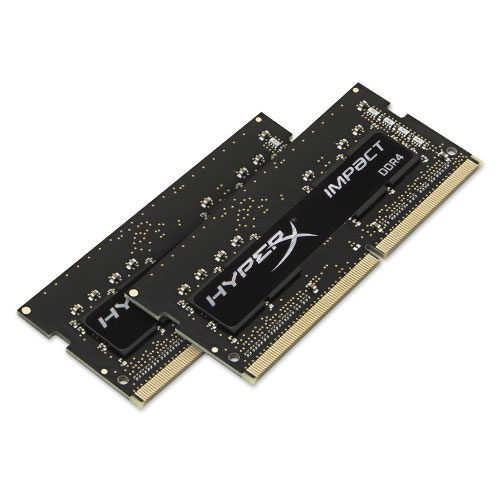 SDRAM DDR4 |
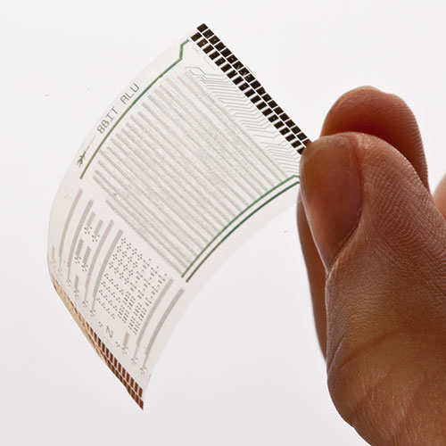 Flexible Memory |
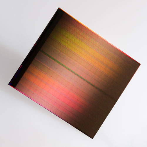 3D Memory |
Williams-Kilburn Tube |
SDRAM DDR4 |
Flexible Memory |
3D Memory |
Williams-Kilburn Tube |
SDRAM DDR4 |
Flexible Memory |
3D Memory |
Williams-Kilburn Tube |
SDRAM DDR4 |
Flexible Memory |
3D Memory |
Williams-Kilburn Tube |
SDRAM DDR4 |
Flexible Memory |
3D Memory |
| Invented in 1946 by Sir Frederic Williams & Tom Kilburn. |
| Invented in 1946 by Sir Frederic Williams & Tom Kilburn. |
| Invented in 1946 by Sir Frederic Williams & Tom Kilburn. |
| Invented in 1946 by Sir Frederic Williams & Tom Kilburn. |
| Invented in 1946 by Sir Frederic Williams & Tom Kilburn. |
 |
|
|
|
|
| Definition: Secondary memory provides a repository for Information, in the form of digital photographs, video, audio, data and programs to be are kept, in a non-volatile form, without power and for a long-term basis. |
| Definition: Secondary memory provides a repository for Information, in the form of digital photographs, video, audio, data and programs to be are kept, in a non-volatile form, without power and for a long-term basis. |
| Definition: Secondary memory provides a repository for Information, in the form of digital photographs, video, audio, data and programs to be are kept, in a non-volatile form, without power and for a long-term basis. |
| Definition: Secondary memory provides a repository for Information, in the form of digital photographs, video, audio, data and programs to be are kept, in a non-volatile form, without power and for a long-term basis. |
| Definition: Secondary memory provides a repository for Information, in the form of digital photographs, video, audio, data and programs to be are kept, in a non-volatile form, without power and for a long-term basis. |
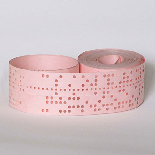 Paper Tape |
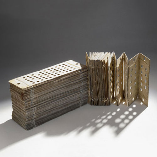 Punched Card |
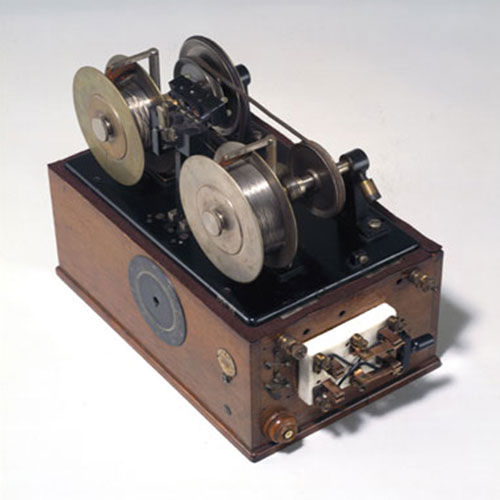 Magnetic Recorder |
 Twister Memory |
Paper Tape |
Punched Card |
Magnetic Recorder |
Twister Memory |
Paper Tape |
Punched Card |
Magnetic Recorder |
Twister Memory |
Paper Tape |
Punched Card |
Magnetic Recorder |
Twister Memory |
Paper Tape |
Punched Card |
Magnetic Recorder |
Twister Memory |
| Paper Tape: 1725, Basile Bouchon, textile worker, invented the first memory encoded device that was used to store instructions for a machine to control and reproduce textile looms. |
| Paper Tape: 1725, Basile Bouchon, textile worker, invented the first memory encoded device that was used to store instructions for a machine to control and reproduce textile looms. |
| Paper Tape: 1725, Basile Bouchon, textile worker, invented the first memory encoded device that was used to store instructions for a machine to control and reproduce textile looms. |
| Paper Tape: 1725, Basile Bouchon, textile worker, invented the first memory encoded device that was used to store instructions for a machine to control and reproduce textile looms. |
| Paper Tape: 1725, Basile Bouchon, textile worker, invented the first memory encoded device that was used to store instructions for a machine to control and reproduce textile looms. |
| Punched Card: 1837, the first memory card, an encoded device used for the first computer in the world, the Analytical Engine, invented by Charles Babbage, Mathematician and Astronomer. The cards were encoded with a hole punch, as read only memory, resulting in a mechanical way to make accurate, lengthy, difficult and time consuming calculations. He later wrote a paper entitled, ‘Theoretical Principles of Machinery for Calculating Tables’. |
| Punched Card: 1837, the first memory card, an encoded device used for the first computer in the world, the Analytical Engine, invented by Charles Babbage, Mathematician and Astronomer. The cards were encoded with a hole punch, as read only memory, resulting in a mechanical way to make accurate, lengthy, difficult and time consuming calculations. He later wrote a paper entitled, ‘Theoretical Principles of Machinery for Calculating Tables’. |
| Punched Card: 1837, the first memory card, an encoded device used for the first computer in the world, the Analytical Engine, invented by Charles Babbage, Mathematician and Astronomer. The cards were encoded with a hole punch, as read only memory, resulting in a mechanical way to make accurate, lengthy, difficult and time consuming calculations. He later wrote a paper entitled, ‘Theoretical Principles of Machinery for Calculating Tables’. |
| Punched Card: 1837, the first memory card, an encoded device used for the first computer in the world, the Analytical Engine, invented by Charles Babbage, Mathematician and Astronomer. The cards were encoded with a hole punch, as read only memory, resulting in a mechanical way to make accurate, lengthy, difficult and time consuming calculations. He later wrote a paper entitled, ‘Theoretical Principles of Machinery for Calculating Tables’. |
| Punched Card: 1837, the first memory card, an encoded device used for the first computer in the world, the Analytical Engine, invented by Charles Babbage, Mathematician and Astronomer. The cards were encoded with a hole punch, as read only memory, resulting in a mechanical way to make accurate, lengthy, difficult and time consuming calculations. He later wrote a paper entitled, ‘Theoretical Principles of Machinery for Calculating Tables’. |
| Magnetic Recorder: 1898, Valdemar Poulsen, Electrical Engineer, developed a magnetic wire recorder in and the first continuous wave radio transmitter, the Poulsen arc transmitter in 1903, which were used in the first broadcasting stations. The magnetic wire medium moves past a recording head as the electrical signal is produced by the sound being recorded by microphone, inducing a magnetic pattern, on the wire, similar to the signal. A playback head translates the changes in the magnetic field from the wire and transforms the electrical signal to sound via a speaker. At the 1900 World’s Fair in Paris, a recording of the voice of Emperor Franz Josef of Austria, is the oldest audio recording to date. |
| Magnetic Recorder: 1898, Valdemar Poulsen, Electrical Engineer, developed a magnetic wire recorder in and the first continuous wave radio transmitter, the Poulsen arc transmitter in 1903, which were used in the first broadcasting stations. The magnetic wire medium moves past a recording head as the electrical signal is produced by the sound being recorded by microphone, inducing a magnetic pattern, on the wire, similar to the signal. A playback head translates the changes in the magnetic field from the wire and transforms the electrical signal to sound via a speaker. At the 1900 World’s Fair in Paris, a recording of the voice of Emperor Franz Josef of Austria, is the oldest audio recording to date. |
| Magnetic Recorder: 1898, Valdemar Poulsen, Electrical Engineer, developed a magnetic wire recorder in and the first continuous wave radio transmitter, the Poulsen arc transmitter in 1903, which were used in the first broadcasting stations. The magnetic wire medium moves past a recording head as the electrical signal is produced by the sound being recorded by microphone, inducing a magnetic pattern, on the wire, similar to the signal. A playback head translates the changes in the magnetic field from the wire and transforms the electrical signal to sound via a speaker. At the 1900 World’s Fair in Paris, a recording of the voice of Emperor Franz Josef of Austria, is the oldest audio recording to date. |
| Magnetic Recorder: 1898, Valdemar Poulsen, Electrical Engineer, developed a magnetic wire recorder in and the first continuous wave radio transmitter, the Poulsen arc transmitter in 1903, which were used in the first broadcasting stations. The magnetic wire medium moves past a recording head as the electrical signal is produced by the sound being recorded by microphone, inducing a magnetic pattern, on the wire, similar to the signal. A playback head translates the changes in the magnetic field from the wire and transforms the electrical signal to sound via a speaker. At the 1900 World’s Fair in Paris, a recording of the voice of Emperor Franz Josef of Austria, is the oldest audio recording to date. |
| Magnetic Recorder: 1898, Valdemar Poulsen, Electrical Engineer, developed a magnetic wire recorder in and the first continuous wave radio transmitter, the Poulsen arc transmitter in 1903, which were used in the first broadcasting stations. The magnetic wire medium moves past a recording head as the electrical signal is produced by the sound being recorded by microphone, inducing a magnetic pattern, on the wire, similar to the signal. A playback head translates the changes in the magnetic field from the wire and transforms the electrical signal to sound via a speaker. At the 1900 World’s Fair in Paris, a recording of the voice of Emperor Franz Josef of Austria, is the oldest audio recording to date. |
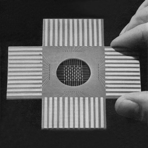
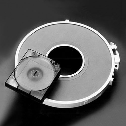
| Twistor Memory: 1957, Andrew Bobeck, Electrical Engineer created this memory, using a grid of magnetic wire interwoven with copper wire and every grid intersection represented one bit. Operationally, twistor was very similar to core memory and was used to make ROM memories, including a re-programmable form known as piggyback twistor. Both forms were able to be manufactured using automated processes, which was expected to lead to much lower production costs than core-based systems. |
| Twistor Memory: 1957, Andrew Bobeck, Electrical Engineer created this memory, using a grid of magnetic wire interwoven with copper wire and every grid intersection represented one bit. Operationally, twistor was very similar to core memory and was used to make ROM memories, including a re-programmable form known as piggyback twistor. Both forms were able to be manufactured using automated processes, which was expected to lead to much lower production costs than core-based systems. |
| Twistor Memory: 1957, Andrew Bobeck, Electrical Engineer created this memory, using a grid of magnetic wire interwoven with copper wire and every grid intersection represented one bit. Operationally, twistor was very similar to core memory and was used to make ROM memories, including a re-programmable form known as piggyback twistor. Both forms were able to be manufactured using automated processes, which was expected to lead to much lower production costs than core-based systems. |
| Twistor Memory: 1957, Andrew Bobeck, Electrical Engineer created this memory, using a grid of magnetic wire interwoven with copper wire and every grid intersection represented one bit. Operationally, twistor was very similar to core memory and was used to make ROM memories, including a re-programmable form known as piggyback twistor. Both forms were able to be manufactured using automated processes, which was expected to lead to much lower production costs than core-based systems. |
| Twistor Memory: 1957, Andrew Bobeck, Electrical Engineer created this memory, using a grid of magnetic wire interwoven with copper wire and every grid intersection represented one bit. Operationally, twistor was very similar to core memory and was used to make ROM memories, including a re-programmable form known as piggyback twistor. Both forms were able to be manufactured using automated processes, which was expected to lead to much lower production costs than core-based systems. |
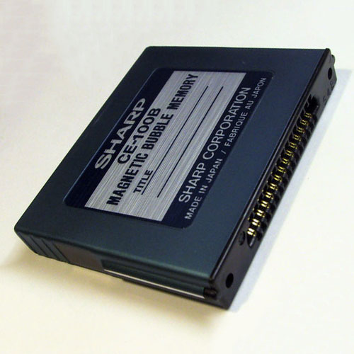 Bubble Memory |
 Magnetic Tape |
 Magnetic Drum |
 Magnetic Core |
Bubble Memory |
Magnetic Tape |
Magnetic Drum |
Magnetic Core |
Bubble Memory |
Magnetic Tape |
Magnetic Drum |
Magnetic Core |
Bubble Memory |
Magnetic Tape |
Magnetic Drum |
Magnetic Core |
Bubble Memory |
Magnetic Tape |
Magnetic Drum |
Magnetic Core |
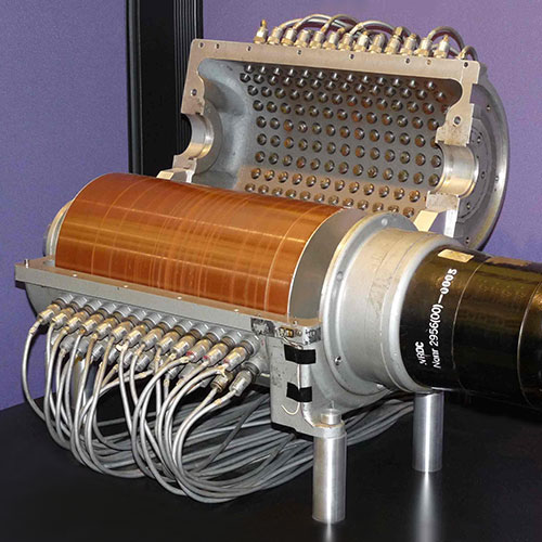
| Bubble Memory: 1974, Andrew Bobeck, Electrical Engineer created a non-volatile computer memory that uses a thin film of a magnetic material to hold bubbles or domains, each storing one bit of data, achieving storage of 4,096 bits per square cm. The material is arranged to form parallel tracks that bubbles can move to with the aid of an external magnetic field. The bubbles are read by moving them to a position on one edge, where they can be read by a magnetic pickup, then rewritten on another edge, to keep the memory cycling through the material. In operation, bubble memories are similar to delay line memory systems. |
| Bubble Memory: 1974, Andrew Bobeck, Electrical Engineer created a non-volatile computer memory that uses a thin film of a magnetic material to hold bubbles or domains, each storing one bit of data, achieving storage of 4,096 bits per square cm. The material is arranged to form parallel tracks that bubbles can move to with the aid of an external magnetic field. The bubbles are read by moving them to a position on one edge, where they can be read by a magnetic pickup, then rewritten on another edge, to keep the memory cycling through the material. In operation, bubble memories are similar to delay line memory systems. |
| Bubble Memory: 1974, Andrew Bobeck, Electrical Engineer created a non-volatile computer memory that uses a thin film of a magnetic material to hold bubbles or domains, each storing one bit of data, achieving storage of 4,096 bits per square cm. The material is arranged to form parallel tracks that bubbles can move to with the aid of an external magnetic field. The bubbles are read by moving them to a position on one edge, where they can be read by a magnetic pickup, then rewritten on another edge, to keep the memory cycling through the material. In operation, bubble memories are similar to delay line memory systems. |
| Bubble Memory: 1974, Andrew Bobeck, Electrical Engineer created a non-volatile computer memory that uses a thin film of a magnetic material to hold bubbles or domains, each storing one bit of data, achieving storage of 4,096 bits per square cm. The material is arranged to form parallel tracks that bubbles can move to with the aid of an external magnetic field. The bubbles are read by moving them to a position on one edge, where they can be read by a magnetic pickup, then rewritten on another edge, to keep the memory cycling through the material. In operation, bubble memories are similar to delay line memory systems. |
| Bubble Memory: 1974, Andrew Bobeck, Electrical Engineer created a non-volatile computer memory that uses a thin film of a magnetic material to hold bubbles or domains, each storing one bit of data, achieving storage of 4,096 bits per square cm. The material is arranged to form parallel tracks that bubbles can move to with the aid of an external magnetic field. The bubbles are read by moving them to a position on one edge, where they can be read by a magnetic pickup, then rewritten on another edge, to keep the memory cycling through the material. In operation, bubble memories are similar to delay line memory systems. |
| Magnetic Tape: 1927, Fritz Pfleumer, Electrical Engineer who invented magnetic tape for recording sound by using very thin paper coated with iron oxide powder with lacquer as glue and in 1932, he granted AEG the right to use his invention when building the world’s first practical tape recorder, the Magnetophon K1. The magnetic tape was first used to record computer data in 1951 on the UNIVAC I, the world’s first commercial computer and comprised of a thin strip of metal, 12.65 mm wide and consisting of nickel-plated bronze (Vicalloy) with a recording density of 198 micrometres/character on eight tracks. |
| Magnetic Tape: 1927, Fritz Pfleumer, Electrical Engineer who invented magnetic tape for recording sound by using very thin paper coated with iron oxide powder with lacquer as glue and in 1932, he granted AEG the right to use his invention when building the world’s first practical tape recorder, the Magnetophon K1. The magnetic tape was first used to record computer data in 1951 on the UNIVAC I, the world’s first commercial computer and comprised of a thin strip of metal, 12.65 mm wide and consisting of nickel-plated bronze (Vicalloy) with a recording density of 198 micrometres/character on eight tracks. |
| Magnetic Tape: 1927, Fritz Pfleumer, Electrical Engineer who invented magnetic tape for recording sound by using very thin paper coated with iron oxide powder with lacquer as glue and in 1932, he granted AEG the right to use his invention when building the world’s first practical tape recorder, the Magnetophon K1. The magnetic tape was first used to record computer data in 1951 on the UNIVAC I, the world’s first commercial computer and comprised of a thin strip of metal, 12.65 mm wide and consisting of nickel-plated bronze (Vicalloy) with a recording density of 198 micrometres/character on eight tracks. |
| Magnetic Tape: 1927, Fritz Pfleumer, Electrical Engineer who invented magnetic tape for recording sound by using very thin paper coated with iron oxide powder with lacquer as glue and in 1932, he granted AEG the right to use his invention when building the world’s first practical tape recorder, the Magnetophon K1. The magnetic tape was first used to record computer data in 1951 on the UNIVAC I, the world’s first commercial computer and comprised of a thin strip of metal, 12.65 mm wide and consisting of nickel-plated bronze (Vicalloy) with a recording density of 198 micrometres/character on eight tracks. |
| Magnetic Tape: 1927, Fritz Pfleumer, Electrical Engineer who invented magnetic tape for recording sound by using very thin paper coated with iron oxide powder with lacquer as glue and in 1932, he granted AEG the right to use his invention when building the world’s first practical tape recorder, the Magnetophon K1. The magnetic tape was first used to record computer data in 1951 on the UNIVAC I, the world’s first commercial computer and comprised of a thin strip of metal, 12.65 mm wide and consisting of nickel-plated bronze (Vicalloy) with a recording density of 198 micrometres/character on eight tracks. |
| Magnetic Drum: 1932, Gustav Tauschek, Electrical Engineer created the first magnetic memory, a data storage device with a capacity of 62.5 kilobytes and in use for forty years, until they were replaced by hard disk drives for secondary storage. The large metallic cylinder was externally coated with a ferromagnetic recording material with one or more read-write heads along the length of the drum, one for each track. As a precursor to the hard disk drive, the drum controller selected the proper head and waited for data to appear. |
| Magnetic Drum: 1932, Gustav Tauschek, Electrical Engineer created the first magnetic memory, a data storage device with a capacity of 62.5 kilobytes and in use for forty years, until they were replaced by hard disk drives for secondary storage. The large metallic cylinder was externally coated with a ferromagnetic recording material with one or more read-write heads along the length of the drum, one for each track. As a precursor to the hard disk drive, the drum controller selected the proper head and waited for data to appear. |
| Magnetic Drum: 1932, Gustav Tauschek, Electrical Engineer created the first magnetic memory, a data storage device with a capacity of 62.5 kilobytes and in use for forty years, until they were replaced by hard disk drives for secondary storage. The large metallic cylinder was externally coated with a ferromagnetic recording material with one or more read-write heads along the length of the drum, one for each track. As a precursor to the hard disk drive, the drum controller selected the proper head and waited for data to appear. |
| Magnetic Drum: 1932, Gustav Tauschek, Electrical Engineer created the first magnetic memory, a data storage device with a capacity of 62.5 kilobytes and in use for forty years, until they were replaced by hard disk drives for secondary storage. The large metallic cylinder was externally coated with a ferromagnetic recording material with one or more read-write heads along the length of the drum, one for each track. As a precursor to the hard disk drive, the drum controller selected the proper head and waited for data to appear. |
| Magnetic Drum: 1932, Gustav Tauschek, Electrical Engineer created the first magnetic memory, a data storage device with a capacity of 62.5 kilobytes and in use for forty years, until they were replaced by hard disk drives for secondary storage. The large metallic cylinder was externally coated with a ferromagnetic recording material with one or more read-write heads along the length of the drum, one for each track. As a precursor to the hard disk drive, the drum controller selected the proper head and waited for data to appear. |
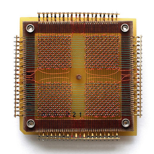
| Magnetic Core: 1951, An Wang, Physicist, created random access memory, core memory, which uses magnetic toroids (cores), through which wires are threaded to read and write information, each core representing one bit of information. The cores are magnetised with two directions, clockwise or counter-clockwise and the resulting bit is stored as zero or one. The reading of each core forces a reset to zero, yet when power is removed, the cores maintain the last value, making this non-volatile random access memory. |
| Magnetic Core: 1951, An Wang, Physicist, created random access memory, core memory, which uses magnetic toroids (cores), through which wires are threaded to read and write information, each core representing one bit of information. The cores are magnetised with two directions, clockwise or counter-clockwise and the resulting bit is stored as zero or one. The reading of each core forces a reset to zero, yet when power is removed, the cores maintain the last value, making this non-volatile random access memory. |
| Magnetic Core: 1951, An Wang, Physicist, created random access memory, core memory, which uses magnetic toroids (cores), through which wires are threaded to read and write information, each core representing one bit of information. The cores are magnetised with two directions, clockwise or counter-clockwise and the resulting bit is stored as zero or one. The reading of each core forces a reset to zero, yet when power is removed, the cores maintain the last value, making this non-volatile random access memory. |
| Magnetic Core: 1951, An Wang, Physicist, created random access memory, core memory, which uses magnetic toroids (cores), through which wires are threaded to read and write information, each core representing one bit of information. The cores are magnetised with two directions, clockwise or counter-clockwise and the resulting bit is stored as zero or one. The reading of each core forces a reset to zero, yet when power is removed, the cores maintain the last value, making this non-volatile random access memory. |
| Magnetic Core: 1951, An Wang, Physicist, created random access memory, core memory, which uses magnetic toroids (cores), through which wires are threaded to read and write information, each core representing one bit of information. The cores are magnetised with two directions, clockwise or counter-clockwise and the resulting bit is stored as zero or one. The reading of each core forces a reset to zero, yet when power is removed, the cores maintain the last value, making this non-volatile random access memory. |
 Delay Line |
 ROM |
 PROM |
 EPROM |
Delay Line |
ROM |
PROM |
EPROM |
Delay Line |
ROM |
PROM |
EPROM |
Delay Line |
ROM |
PROM |
EPROM |
Delay Line |
ROM |
PROM |
EPROM |
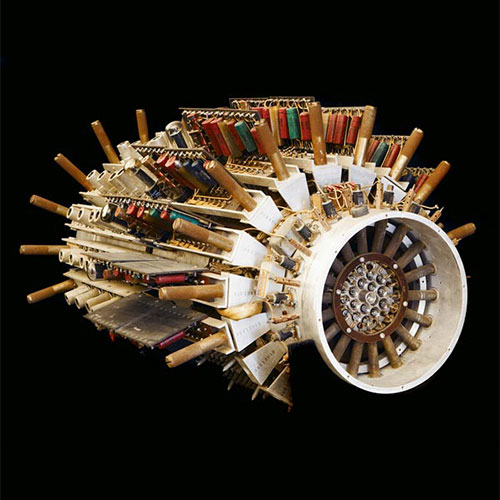
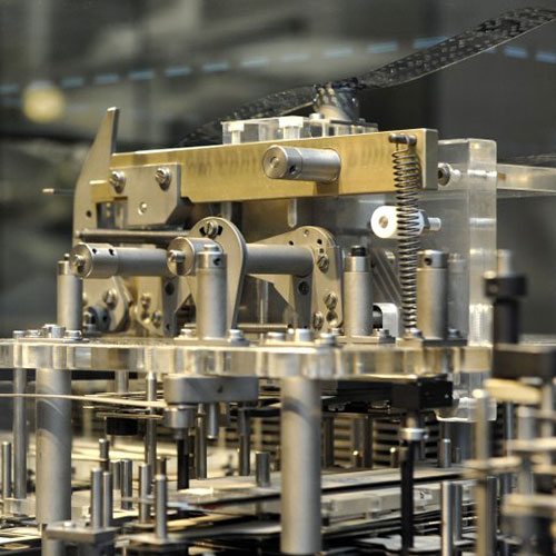
| Mercury Delay Line Memory: 1947, John Presper Eckert, Electrical Engineer and John Mauchly, Physicist created this memory for the EDVAC, UNIVAC I and EDSAC computer systems. The Mercury Memory of magnetostrictive delay lines, required the use of rotating disks to transfer data to a read head at one point on the circumference to a write head further along. As timing is critical, the “cycle time” needed to complete an operation is calibrated to the time required for the task to read or write memory. Delay lines were timed to receive pulses to be read at a determined tolerance to read it, counting pulses and comparing to a master clock to find a particular bit. Mercury was chosen for the acoustic impedance properties that closely match that of piezoelectric quartz crystals and with minimum energy loss no echo, the signal could be transmitted from the crystal to the medium and back, with minimal degradation. The high speed of sound in mercury at 1,450 m/s meant that the time required to wait for a pulse to arrive and number of pulses stored was limited. The UNIVAC I had column stored 120 bits, requiring seven large memory units with 18 columns each to make up a 1000-word store and an average access time of 300 microseconds. The EDSAC was the second full scale stored-program digital computer and began operation with 512, 35-bit words of memory, stored in 32 delay lines holding 576 bits each (36th bit as a start/stop bit to every word) and an average access time of 222 microseconds. |
| Mercury Delay Line Memory: 1947, John Presper Eckert, Electrical Engineer and John Mauchly, Physicist created this memory for the EDVAC, UNIVAC I and EDSAC computer systems. The Mercury Memory of magnetostrictive delay lines, required the use of rotating disks to transfer data to a read head at one point on the circumference to a write head further along. As timing is critical, the “cycle time” needed to complete an operation is calibrated to the time required for the task to read or write memory. Delay lines were timed to receive pulses to be read at a determined tolerance to read it, counting pulses and comparing to a master clock to find a particular bit. Mercury was chosen for the acoustic impedance properties that closely match that of piezoelectric quartz crystals and with minimum energy loss no echo, the signal could be transmitted from the crystal to the medium and back, with minimal degradation. The high speed of sound in mercury at 1,450 m/s meant that the time required to wait for a pulse to arrive and number of pulses stored was limited. The UNIVAC I had column stored 120 bits, requiring seven large memory units with 18 columns each to make up a 1000-word store and an average access time of 300 microseconds. The EDSAC was the second full scale stored-program digital computer and began operation with 512, 35-bit words of memory, stored in 32 delay lines holding 576 bits each (36th bit as a start/stop bit to every word) and an average access time of 222 microseconds. |
| Mercury Delay Line Memory: 1947, John Presper Eckert, Electrical Engineer and John Mauchly, Physicist created this memory for the EDVAC, UNIVAC I and EDSAC computer systems. The Mercury Memory of magnetostrictive delay lines, required the use of rotating disks to transfer data to a read head at one point on the circumference to a write head further along. As timing is critical, the “cycle time” needed to complete an operation is calibrated to the time required for the task to read or write memory. Delay lines were timed to receive pulses to be read at a determined tolerance to read it, counting pulses and comparing to a master clock to find a particular bit. Mercury was chosen for the acoustic impedance properties that closely match that of piezoelectric quartz crystals and with minimum energy loss no echo, the signal could be transmitted from the crystal to the medium and back, with minimal degradation. The high speed of sound in mercury at 1,450 m/s meant that the time required to wait for a pulse to arrive and number of pulses stored was limited. The UNIVAC I had column stored 120 bits, requiring seven large memory units with 18 columns each to make up a 1000-word store and an average access time of 300 microseconds. The EDSAC was the second full scale stored-program digital computer and began operation with 512, 35-bit words of memory, stored in 32 delay lines holding 576 bits each (36th bit as a start/stop bit to every word) and an average access time of 222 microseconds. |
| Mercury Delay Line Memory: 1947, John Presper Eckert, Electrical Engineer and John Mauchly, Physicist created this memory for the EDVAC, UNIVAC I and EDSAC computer systems. The Mercury Memory of magnetostrictive delay lines, required the use of rotating disks to transfer data to a read head at one point on the circumference to a write head further along. As timing is critical, the “cycle time” needed to complete an operation is calibrated to the time required for the task to read or write memory. Delay lines were timed to receive pulses to be read at a determined tolerance to read it, counting pulses and comparing to a master clock to find a particular bit. Mercury was chosen for the acoustic impedance properties that closely match that of piezoelectric quartz crystals and with minimum energy loss no echo, the signal could be transmitted from the crystal to the medium and back, with minimal degradation. The high speed of sound in mercury at 1,450 m/s meant that the time required to wait for a pulse to arrive and number of pulses stored was limited. The UNIVAC I had column stored 120 bits, requiring seven large memory units with 18 columns each to make up a 1000-word store and an average access time of 300 microseconds. The EDSAC was the second full scale stored-program digital computer and began operation with 512, 35-bit words of memory, stored in 32 delay lines holding 576 bits each (36th bit as a start/stop bit to every word) and an average access time of 222 microseconds. |
| Mercury Delay Line Memory: 1947, John Presper Eckert, Electrical Engineer and John Mauchly, Physicist created this memory for the EDVAC, UNIVAC I and EDSAC computer systems. The Mercury Memory of magnetostrictive delay lines, required the use of rotating disks to transfer data to a read head at one point on the circumference to a write head further along. As timing is critical, the “cycle time” needed to complete an operation is calibrated to the time required for the task to read or write memory. Delay lines were timed to receive pulses to be read at a determined tolerance to read it, counting pulses and comparing to a master clock to find a particular bit. Mercury was chosen for the acoustic impedance properties that closely match that of piezoelectric quartz crystals and with minimum energy loss no echo, the signal could be transmitted from the crystal to the medium and back, with minimal degradation. The high speed of sound in mercury at 1,450 m/s meant that the time required to wait for a pulse to arrive and number of pulses stored was limited. The UNIVAC I had column stored 120 bits, requiring seven large memory units with 18 columns each to make up a 1000-word store and an average access time of 300 microseconds. The EDSAC was the second full scale stored-program digital computer and began operation with 512, 35-bit words of memory, stored in 32 delay lines holding 576 bits each (36th bit as a start/stop bit to every word) and an average access time of 222 microseconds. |
| Read Only Memory ROM: 1938, by Konrad Zuse, Civil Engineer, created the Z1, the first fully operational programmable electromechanical computer, based on binary floating point numbers, binary switching system, electric motor for a clock frequency of 1 Hz (cycle per second) and a keyboard for data input and programs stored on punch tapes by means of an 8-bit code. The relays in the data storage memory consisted of a number of thin strips of metal lying between two plates of glass, 5mm apart, in one direction through this layer represent 16 cells, each containing one numerical quantity, whilst those perpendicular represent the individual digits of each cell. Motion of the strips is controlled by electromagnetic relays that engage or disengage individual strips with an arm providing mechanical impulses at regular intervals and it would appear that motion of a particular strip representing a chosen cell exposes other moving parts, corresponding to each digit position in the cell, to the motion communicated by the various transverse digit strips. In 1964, a Transformer Read Only Storage TROS module, created by Charles Owen, Daniel Taub and William Warwick of IBM, would read each bit of this read-only memory from punches mylar strips, controlling the current flow through the transformer or around it, representing a binary zero or a one. In 1966, a Charged Capacitor Read Only Score CCROS was a capacitor matrix with a changeable element in an etched or printed Mylar Card that is “punched out” to reveal a coded ROM. The CCROS System created by Duane Baxter, Bruce Felton, Harold Hill and Harry Hoffman of IBM, utilises 12, 60-bit words in 336 cards throughout 42 boards, resulting in a total of 4032 words and each word could be read every 750 nanoseconds. |
| Read Only Memory ROM: 1938, by Konrad Zuse, Civil Engineer, created the Z1, the first fully operational programmable electromechanical computer, based on binary floating point numbers, binary switching system, electric motor for a clock frequency of 1 Hz (cycle per second) and a keyboard for data input and programs stored on punch tapes by means of an 8-bit code. The relays in the data storage memory consisted of a number of thin strips of metal lying between two plates of glass, 5mm apart, in one direction through this layer represent 16 cells, each containing one numerical quantity, whilst those perpendicular represent the individual digits of each cell. Motion of the strips is controlled by electromagnetic relays that engage or disengage individual strips with an arm providing mechanical impulses at regular intervals and it would appear that motion of a particular strip representing a chosen cell exposes other moving parts, corresponding to each digit position in the cell, to the motion communicated by the various transverse digit strips. In 1964, a Transformer Read Only Storage TROS module, created by Charles Owen, Daniel Taub and William Warwick of IBM, would read each bit of this read-only memory from punches mylar strips, controlling the current flow through the transformer or around it, representing a binary zero or a one. In 1966, a Charged Capacitor Read Only Score CCROS was a capacitor matrix with a changeable element in an etched or printed Mylar Card that is “punched out” to reveal a coded ROM. The CCROS System created by Duane Baxter, Bruce Felton, Harold Hill and Harry Hoffman of IBM, utilises 12, 60-bit words in 336 cards throughout 42 boards, resulting in a total of 4032 words and each word could be read every 750 nanoseconds. |
| Read Only Memory ROM: 1938, by Konrad Zuse, Civil Engineer, created the Z1, the first fully operational programmable electromechanical computer, based on binary floating point numbers, binary switching system, electric motor for a clock frequency of 1 Hz (cycle per second) and a keyboard for data input and programs stored on punch tapes by means of an 8-bit code. The relays in the data storage memory consisted of a number of thin strips of metal lying between two plates of glass, 5mm apart, in one direction through this layer represent 16 cells, each containing one numerical quantity, whilst those perpendicular represent the individual digits of each cell. Motion of the strips is controlled by electromagnetic relays that engage or disengage individual strips with an arm providing mechanical impulses at regular intervals and it would appear that motion of a particular strip representing a chosen cell exposes other moving parts, corresponding to each digit position in the cell, to the motion communicated by the various transverse digit strips. In 1964, a Transformer Read Only Storage TROS module, created by Charles Owen, Daniel Taub and William Warwick of IBM, would read each bit of this read-only memory from punches mylar strips, controlling the current flow through the transformer or around it, representing a binary zero or a one. In 1966, a Charged Capacitor Read Only Score CCROS was a capacitor matrix with a changeable element in an etched or printed Mylar Card that is “punched out” to reveal a coded ROM. The CCROS System created by Duane Baxter, Bruce Felton, Harold Hill and Harry Hoffman of IBM, utilises 12, 60-bit words in 336 cards throughout 42 boards, resulting in a total of 4032 words and each word could be read every 750 nanoseconds. |
| Read Only Memory ROM: 1938, by Konrad Zuse, Civil Engineer, created the Z1, the first fully operational programmable electromechanical computer, based on binary floating point numbers, binary switching system, electric motor for a clock frequency of 1 Hz (cycle per second) and a keyboard for data input and programs stored on punch tapes by means of an 8-bit code. The relays in the data storage memory consisted of a number of thin strips of metal lying between two plates of glass, 5mm apart, in one direction through this layer represent 16 cells, each containing one numerical quantity, whilst those perpendicular represent the individual digits of each cell. Motion of the strips is controlled by electromagnetic relays that engage or disengage individual strips with an arm providing mechanical impulses at regular intervals and it would appear that motion of a particular strip representing a chosen cell exposes other moving parts, corresponding to each digit position in the cell, to the motion communicated by the various transverse digit strips. In 1964, a Transformer Read Only Storage TROS module, created by Charles Owen, Daniel Taub and William Warwick of IBM, would read each bit of this read-only memory from punches mylar strips, controlling the current flow through the transformer or around it, representing a binary zero or a one. In 1966, a Charged Capacitor Read Only Score CCROS was a capacitor matrix with a changeable element in an etched or printed Mylar Card that is “punched out” to reveal a coded ROM. The CCROS System created by Duane Baxter, Bruce Felton, Harold Hill and Harry Hoffman of IBM, utilises 12, 60-bit words in 336 cards throughout 42 boards, resulting in a total of 4032 words and each word could be read every 750 nanoseconds. |
| Read Only Memory ROM: 1938, by Konrad Zuse, Civil Engineer, created the Z1, the first fully operational programmable electromechanical computer, based on binary floating point numbers, binary switching system, electric motor for a clock frequency of 1 Hz (cycle per second) and a keyboard for data input and programs stored on punch tapes by means of an 8-bit code. The relays in the data storage memory consisted of a number of thin strips of metal lying between two plates of glass, 5mm apart, in one direction through this layer represent 16 cells, each containing one numerical quantity, whilst those perpendicular represent the individual digits of each cell. Motion of the strips is controlled by electromagnetic relays that engage or disengage individual strips with an arm providing mechanical impulses at regular intervals and it would appear that motion of a particular strip representing a chosen cell exposes other moving parts, corresponding to each digit position in the cell, to the motion communicated by the various transverse digit strips. In 1964, a Transformer Read Only Storage TROS module, created by Charles Owen, Daniel Taub and William Warwick of IBM, would read each bit of this read-only memory from punches mylar strips, controlling the current flow through the transformer or around it, representing a binary zero or a one. In 1966, a Charged Capacitor Read Only Score CCROS was a capacitor matrix with a changeable element in an etched or printed Mylar Card that is “punched out” to reveal a coded ROM. The CCROS System created by Duane Baxter, Bruce Felton, Harold Hill and Harry Hoffman of IBM, utilises 12, 60-bit words in 336 cards throughout 42 boards, resulting in a total of 4032 words and each word could be read every 750 nanoseconds. |
| Programmable Read Only Memory PROM: 1956, by Wen Tsing Chow, Electrical Engineer was conceived at the request of the United States Air Force arrive at a flexible secure way of storing targeting constants in the Atlas E/F ICBM’s airborne digital computer. The term “burn”, refers to the process of programming a PROM, as the original implementation was to burn the internal whiskers of diodes with a current overload to produce a circuit discontinuity. |
| Programmable Read Only Memory PROM: 1956, by Wen Tsing Chow, Electrical Engineer was conceived at the request of the United States Air Force arrive at a flexible secure way of storing targeting constants in the Atlas E/F ICBM’s airborne digital computer. The term “burn”, refers to the process of programming a PROM, as the original implementation was to burn the internal whiskers of diodes with a current overload to produce a circuit discontinuity. |
| Programmable Read Only Memory PROM: 1956, by Wen Tsing Chow, Electrical Engineer was conceived at the request of the United States Air Force arrive at a flexible secure way of storing targeting constants in the Atlas E/F ICBM’s airborne digital computer. The term “burn”, refers to the process of programming a PROM, as the original implementation was to burn the internal whiskers of diodes with a current overload to produce a circuit discontinuity. |
| Programmable Read Only Memory PROM: 1956, by Wen Tsing Chow, Electrical Engineer was conceived at the request of the United States Air Force arrive at a flexible secure way of storing targeting constants in the Atlas E/F ICBM’s airborne digital computer. The term “burn”, refers to the process of programming a PROM, as the original implementation was to burn the internal whiskers of diodes with a current overload to produce a circuit discontinuity. |
| Programmable Read Only Memory PROM: 1956, by Wen Tsing Chow, Electrical Engineer was conceived at the request of the United States Air Force arrive at a flexible secure way of storing targeting constants in the Atlas E/F ICBM’s airborne digital computer. The term “burn”, refers to the process of programming a PROM, as the original implementation was to burn the internal whiskers of diodes with a current overload to produce a circuit discontinuity. |
| Erasable Programmable Read Only Memory EPROM: 1971, by Dov Frohman, Electrical Engineer created non-volatile memory as an array of floating-gate transistors individually programmed by an electronic device that supplies higher voltages than those normally used in digital circuits. Once programmed, the EPROM can be erased by exposing it to strong ultraviolet light through a transparent fused quartz window in the top of the package, through which the silicon chip is visible. |
| Erasable Programmable Read Only Memory EPROM: 1971, by Dov Frohman, Electrical Engineer created non-volatile memory as an array of floating-gate transistors individually programmed by an electronic device that supplies higher voltages than those normally used in digital circuits. Once programmed, the EPROM can be erased by exposing it to strong ultraviolet light through a transparent fused quartz window in the top of the package, through which the silicon chip is visible. |
| Erasable Programmable Read Only Memory EPROM: 1971, by Dov Frohman, Electrical Engineer created non-volatile memory as an array of floating-gate transistors individually programmed by an electronic device that supplies higher voltages than those normally used in digital circuits. Once programmed, the EPROM can be erased by exposing it to strong ultraviolet light through a transparent fused quartz window in the top of the package, through which the silicon chip is visible. |
| Erasable Programmable Read Only Memory EPROM: 1971, by Dov Frohman, Electrical Engineer created non-volatile memory as an array of floating-gate transistors individually programmed by an electronic device that supplies higher voltages than those normally used in digital circuits. Once programmed, the EPROM can be erased by exposing it to strong ultraviolet light through a transparent fused quartz window in the top of the package, through which the silicon chip is visible. |
| Erasable Programmable Read Only Memory EPROM: 1971, by Dov Frohman, Electrical Engineer created non-volatile memory as an array of floating-gate transistors individually programmed by an electronic device that supplies higher voltages than those normally used in digital circuits. Once programmed, the EPROM can be erased by exposing it to strong ultraviolet light through a transparent fused quartz window in the top of the package, through which the silicon chip is visible. |
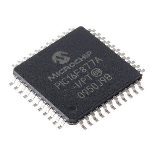 EEPROM |
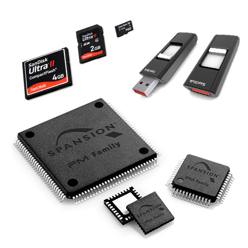 Flash |
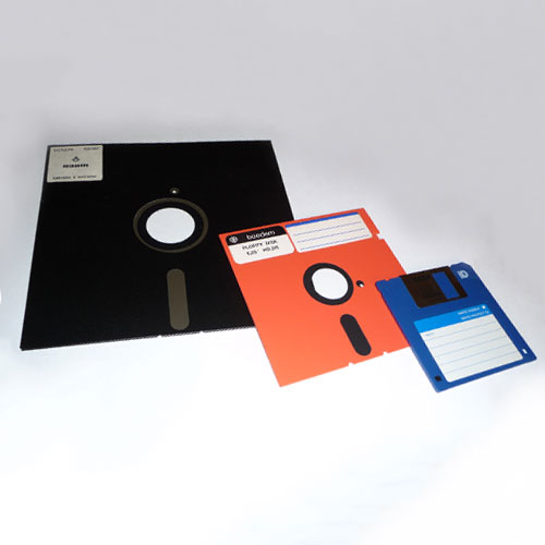 Floppy Disk |
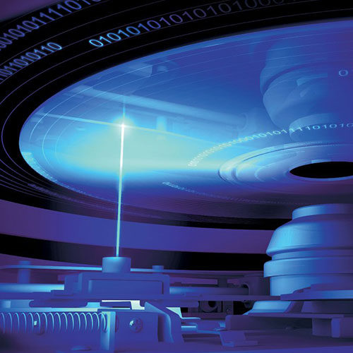 Optical Disk |
EEPROM |
Flash |
Floppy Disk |
Optical Disk |
EEPROM |
Flash |
Floppy Disk |
Optical Disk |
EEPROM |
Flash |
Floppy Disk |
Optical Disk |
EEPROM |
Flash |
Floppy Disk |
Optical Disk |
| Electrically Erasable Programmable Read Only Memory EPROM: 1977, by Eli Harari, Physicist & Mathematician created non-volatile memory as an array of floating-gate transistors individually programmed by an electronic device that supplies higher voltages than those normally used in digital circuits. Once programmed, the EEPROM can allow individual bytes to be erased and reprogrammed. EEPROMs can be programmed and erased in-circuit, by applying special programming signals and allows for multi-byte page operations. The life for erasing and reprogramming an EEPROM is now reaching a million operations. |
| Electrically Erasable Programmable Read Only Memory EPROM: 1977, by Eli Harari, Physicist & Mathematician created non-volatile memory as an array of floating-gate transistors individually programmed by an electronic device that supplies higher voltages than those normally used in digital circuits. Once programmed, the EEPROM can allow individual bytes to be erased and reprogrammed. EEPROMs can be programmed and erased in-circuit, by applying special programming signals and allows for multi-byte page operations. The life for erasing and reprogramming an EEPROM is now reaching a million operations. |
| Electrically Erasable Programmable Read Only Memory EPROM: 1977, by Eli Harari, Physicist & Mathematician created non-volatile memory as an array of floating-gate transistors individually programmed by an electronic device that supplies higher voltages than those normally used in digital circuits. Once programmed, the EEPROM can allow individual bytes to be erased and reprogrammed. EEPROMs can be programmed and erased in-circuit, by applying special programming signals and allows for multi-byte page operations. The life for erasing and reprogramming an EEPROM is now reaching a million operations. |
| Electrically Erasable Programmable Read Only Memory EPROM: 1977, by Eli Harari, Physicist & Mathematician created non-volatile memory as an array of floating-gate transistors individually programmed by an electronic device that supplies higher voltages than those normally used in digital circuits. Once programmed, the EEPROM can allow individual bytes to be erased and reprogrammed. EEPROMs can be programmed and erased in-circuit, by applying special programming signals and allows for multi-byte page operations. The life for erasing and reprogramming an EEPROM is now reaching a million operations. |
| Electrically Erasable Programmable Read Only Memory EPROM: 1977, by Eli Harari, Physicist & Mathematician created non-volatile memory as an array of floating-gate transistors individually programmed by an electronic device that supplies higher voltages than those normally used in digital circuits. Once programmed, the EEPROM can allow individual bytes to be erased and reprogrammed. EEPROMs can be programmed and erased in-circuit, by applying special programming signals and allows for multi-byte page operations. The life for erasing and reprogramming an EEPROM is now reaching a million operations. |
| Flash Memory: 1980, by Fujio Masuoka, Electrical Engineer, developed flash memory from an EEPROM. With two main types of flash memory, NAND and NOR logic gates, individual flash memory cells exhibit internal characteristics similar to those of the corresponding gates. The NAND type is primarily used in memory cards, USB flash drives, solid-state drives, for general storage and transfer of data. NAND or NOR flash memory is also often used to store configuration data in numerous digital products, previously made possible by EEPROM or battery-powered static RAM. In addition to being non-volatile, flash memory offers fast read access times and mechanical shock resistance. It is portable, does not require power, highly durable and is able to withstand high pressure, temperature and immersion in water. |
| Flash Memory: 1980, by Fujio Masuoka, Electrical Engineer, developed flash memory from an EEPROM. With two main types of flash memory, NAND and NOR logic gates, individual flash memory cells exhibit internal characteristics similar to those of the corresponding gates. The NAND type is primarily used in memory cards, USB flash drives, solid-state drives, for general storage and transfer of data. NAND or NOR flash memory is also often used to store configuration data in numerous digital products, previously made possible by EEPROM or battery-powered static RAM. In addition to being non-volatile, flash memory offers fast read access times and mechanical shock resistance. It is portable, does not require power, highly durable and is able to withstand high pressure, temperature and immersion in water. |
| Flash Memory: 1980, by Fujio Masuoka, Electrical Engineer, developed flash memory from an EEPROM. With two main types of flash memory, NAND and NOR logic gates, individual flash memory cells exhibit internal characteristics similar to those of the corresponding gates. The NAND type is primarily used in memory cards, USB flash drives, solid-state drives, for general storage and transfer of data. NAND or NOR flash memory is also often used to store configuration data in numerous digital products, previously made possible by EEPROM or battery-powered static RAM. In addition to being non-volatile, flash memory offers fast read access times and mechanical shock resistance. It is portable, does not require power, highly durable and is able to withstand high pressure, temperature and immersion in water. |
| Flash Memory: 1980, by Fujio Masuoka, Electrical Engineer, developed flash memory from an EEPROM. With two main types of flash memory, NAND and NOR logic gates, individual flash memory cells exhibit internal characteristics similar to those of the corresponding gates. The NAND type is primarily used in memory cards, USB flash drives, solid-state drives, for general storage and transfer of data. NAND or NOR flash memory is also often used to store configuration data in numerous digital products, previously made possible by EEPROM or battery-powered static RAM. In addition to being non-volatile, flash memory offers fast read access times and mechanical shock resistance. It is portable, does not require power, highly durable and is able to withstand high pressure, temperature and immersion in water. |
| Flash Memory: 1980, by Fujio Masuoka, Electrical Engineer, developed flash memory from an EEPROM. With two main types of flash memory, NAND and NOR logic gates, individual flash memory cells exhibit internal characteristics similar to those of the corresponding gates. The NAND type is primarily used in memory cards, USB flash drives, solid-state drives, for general storage and transfer of data. NAND or NOR flash memory is also often used to store configuration data in numerous digital products, previously made possible by EEPROM or battery-powered static RAM. In addition to being non-volatile, flash memory offers fast read access times and mechanical shock resistance. It is portable, does not require power, highly durable and is able to withstand high pressure, temperature and immersion in water. |
| Floppy Disk: 1971, Alan Shugart, Electrical Engineer, introduced the first 8-inch floppy disks, a flexible plastic disk coated with magnetic iron oxide with an initial capacity of 80kb, then climbing to 1.2Mb. In 1976, the 5¼ inch floppy disks ranged from 110kb to 1.2Mb and then in 1982, the 3½ inch floppy disk spanned from 264kb to 2.88Mb, 21Mb for the Floptical, 120Mb and 240Mb for the LS Drives. |
| Floppy Disk: 1971, Alan Shugart, Electrical Engineer, introduced the first 8-inch floppy disks, a flexible plastic disk coated with magnetic iron oxide with an initial capacity of 80kb, then climbing to 1.2Mb. In 1976, the 5¼ inch floppy disks ranged from 110kb to 1.2Mb and then in 1982, the 3½ inch floppy disk spanned from 264kb to 2.88Mb, 21Mb for the Floptical, 120Mb and 240Mb for the LS Drives. |
| Floppy Disk: 1971, Alan Shugart, Electrical Engineer, introduced the first 8-inch floppy disks, a flexible plastic disk coated with magnetic iron oxide with an initial capacity of 80kb, then climbing to 1.2Mb. In 1976, the 5¼ inch floppy disks ranged from 110kb to 1.2Mb and then in 1982, the 3½ inch floppy disk spanned from 264kb to 2.88Mb, 21Mb for the Floptical, 120Mb and 240Mb for the LS Drives. |
| Floppy Disk: 1971, Alan Shugart, Electrical Engineer, introduced the first 8-inch floppy disks, a flexible plastic disk coated with magnetic iron oxide with an initial capacity of 80kb, then climbing to 1.2Mb. In 1976, the 5¼ inch floppy disks ranged from 110kb to 1.2Mb and then in 1982, the 3½ inch floppy disk spanned from 264kb to 2.88Mb, 21Mb for the Floptical, 120Mb and 240Mb for the LS Drives. |
| Floppy Disk: 1971, Alan Shugart, Electrical Engineer, introduced the first 8-inch floppy disks, a flexible plastic disk coated with magnetic iron oxide with an initial capacity of 80kb, then climbing to 1.2Mb. In 1976, the 5¼ inch floppy disks ranged from 110kb to 1.2Mb and then in 1982, the 3½ inch floppy disk spanned from 264kb to 2.88Mb, 21Mb for the Floptical, 120Mb and 240Mb for the LS Drives. |
| Optical Disk: 1958, David Paul Gregg, Physicist was the inventor of the Optical disc and within 10 years, his designs and patents paved the way for the Laserdisc. In 1965, James Russell, Physicist created an early prototype that used a laser to write a binary pattern onto a photosensitive plate, one micrometre wide and read by an illuminated light source at the back of the transparent foil, resulting in low information density. 1968, Adrianus Korpel, Electrical Engineer with Zenith Electronics Corporation, created the videodisc with holographic storage. In 1969, physicists Klaas Compaan and Piet Kramer of Philips, recorded video images in holographic form, using a laser beam in reflective mode to read a track of pits using an FM video signal. Philips and MCA brought the optical Videodisk to market in 1978. Sony and Philips created a taskforce to develop a high density low cost audio disk and in 1982, the Compact Disc (CD) was released. Made from polycarbonate plastic, 120mm in diameter, 1.2mm thick and spindle hole of 15 mm, radiates out to the first-transition area, the clamping ring, the clamping area, the second-transition area, mirror band, data area, then the rim to occupy a radius from 25 to 58 mm. A thin layer of aluminium or gold is applied to the surface, then protected by a film of lacquer spin coated directly on the reflective layer with the label printed on the lacquer layer by screen or offset print. The data on a CD is represented as tiny indentations, “pits”, encoded in a spiral track moulded into the top of the polycarbonate layer and between pits are areas known as “lands”. Each pit is approximately 100 nm deep by 500 nm wide, and varies from 850 nm to 3.5 µm in length, with a pitch (distance between tracks) of 1.6 µm. The CD is read by focusing a 780 nm wavelength (near infrared) laser through the polycarbonate layer to measure the change in height between pits and lands by reflected light and with measuring the intensity change with a photodiode, the data can be read. Program Area of 86.05 cm2 / Pitch of 1.6 µm = Data Length of 5.38 km / Scanning Speed of 1.2m/s = Playing Time of 74 Minutes (650MB). The CD ROM, first-generation optical drive was created to store high density low cost audio. With a red laser with a wavelength of 780nm and focus of 1.6µm, allowed for 650 MB to 900 MB storage on a 120 mm polycarbonate plastic disc. The DVD, second-generation optical drive was created to store broadcast-quality digital video. With a red laser with a wavelength of 400nm and focus of 1.2µm, allowed for 4.7 GB to 17 GB storage on a 120 mm polycarbonate plastic disc. The Blue-ray, third-generation optical drive was created to store high definition video and greater data capacities. With a blue-violet laser with a wavelength of 150nm and focus of 480nm, allowed for 25 GB to 128 GB storage on a 120 mm polycarbonate plastic disc. The Holographic Versatile Disc, fourth-generation optical drive was created to store video. holograms and data. With a green and red laser collimated in a single beam, allowing for 100 GB to 6 TB storage on a 120 mm polycarbonate plastic disc. |
| Optical Disk: 1958, David Paul Gregg, Physicist was the inventor of the Optical disc and within 10 years, his designs and patents paved the way for the Laserdisc. In 1965, James Russell, Physicist created an early prototype that used a laser to write a binary pattern onto a photosensitive plate, one micrometre wide and read by an illuminated light source at the back of the transparent foil, resulting in low information density. 1968, Adrianus Korpel, Electrical Engineer with Zenith Electronics Corporation, created the videodisc with holographic storage. In 1969, physicists Klaas Compaan and Piet Kramer of Philips, recorded video images in holographic form, using a laser beam in reflective mode to read a track of pits using an FM video signal. Philips and MCA brought the optical Videodisk to market in 1978. Sony and Philips created a taskforce to develop a high density low cost audio disk and in 1982, the Compact Disc (CD) was released. Made from polycarbonate plastic, 120mm in diameter, 1.2mm thick and spindle hole of 15 mm, radiates out to the first-transition area, the clamping ring, the clamping area, the second-transition area, mirror band, data area, then the rim to occupy a radius from 25 to 58 mm. A thin layer of aluminium or gold is applied to the surface, then protected by a film of lacquer spin coated directly on the reflective layer with the label printed on the lacquer layer by screen or offset print. The data on a CD is represented as tiny indentations, “pits”, encoded in a spiral track moulded into the top of the polycarbonate layer and between pits are areas known as “lands”. Each pit is approximately 100 nm deep by 500 nm wide, and varies from 850 nm to 3.5 µm in length, with a pitch (distance between tracks) of 1.6 µm. The CD is read by focusing a 780 nm wavelength (near infrared) laser through the polycarbonate layer to measure the change in height between pits and lands by reflected light and with measuring the intensity change with a photodiode, the data can be read. Program Area of 86.05 cm2 / Pitch of 1.6 µm = Data Length of 5.38 km / Scanning Speed of 1.2m/s = Playing Time of 74 Minutes (650MB). The CD ROM, first-generation optical drive was created to store high density low cost audio. With a red laser with a wavelength of 780nm and focus of 1.6µm, allowed for 650 MB to 900 MB storage on a 120 mm polycarbonate plastic disc. The DVD, second-generation optical drive was created to store broadcast-quality digital video. With a red laser with a wavelength of 400nm and focus of 1.2µm, allowed for 4.7 GB to 17 GB storage on a 120 mm polycarbonate plastic disc. The Blue-ray, third-generation optical drive was created to store high definition video and greater data capacities. With a blue-violet laser with a wavelength of 150nm and focus of 480nm, allowed for 25 GB to 128 GB storage on a 120 mm polycarbonate plastic disc. The Holographic Versatile Disc, fourth-generation optical drive was created to store video. holograms and data. With a green and red laser collimated in a single beam, allowing for 100 GB to 6 TB storage on a 120 mm polycarbonate plastic disc. |
| Optical Disk: 1958, David Paul Gregg, Physicist was the inventor of the Optical disc and within 10 years, his designs and patents paved the way for the Laserdisc. In 1965, James Russell, Physicist created an early prototype that used a laser to write a binary pattern onto a photosensitive plate, one micrometre wide and read by an illuminated light source at the back of the transparent foil, resulting in low information density. 1968, Adrianus Korpel, Electrical Engineer with Zenith Electronics Corporation, created the videodisc with holographic storage. In 1969, physicists Klaas Compaan and Piet Kramer of Philips, recorded video images in holographic form, using a laser beam in reflective mode to read a track of pits using an FM video signal. Philips and MCA brought the optical Videodisk to market in 1978. Sony and Philips created a taskforce to develop a high density low cost audio disk and in 1982, the Compact Disc (CD) was released. Made from polycarbonate plastic, 120mm in diameter, 1.2mm thick and spindle hole of 15 mm, radiates out to the first-transition area, the clamping ring, the clamping area, the second-transition area, mirror band, data area, then the rim to occupy a radius from 25 to 58 mm. A thin layer of aluminium or gold is applied to the surface, then protected by a film of lacquer spin coated directly on the reflective layer with the label printed on the lacquer layer by screen or offset print. The data on a CD is represented as tiny indentations, “pits”, encoded in a spiral track moulded into the top of the polycarbonate layer and between pits are areas known as “lands”. Each pit is approximately 100 nm deep by 500 nm wide, and varies from 850 nm to 3.5 µm in length, with a pitch (distance between tracks) of 1.6 µm. The CD is read by focusing a 780 nm wavelength (near infrared) laser through the polycarbonate layer to measure the change in height between pits and lands by reflected light and with measuring the intensity change with a photodiode, the data can be read. Program Area of 86.05 cm2 / Pitch of 1.6 µm = Data Length of 5.38 km / Scanning Speed of 1.2m/s = Playing Time of 74 Minutes (650MB). The CD ROM, first-generation optical drive was created to store high density low cost audio. With a red laser with a wavelength of 780nm and focus of 1.6µm, allowed for 650 MB to 900 MB storage on a 120 mm polycarbonate plastic disc. The DVD, second-generation optical drive was created to store broadcast-quality digital video. With a red laser with a wavelength of 400nm and focus of 1.2µm, allowed for 4.7 GB to 17 GB storage on a 120 mm polycarbonate plastic disc. The Blue-ray, third-generation optical drive was created to store high definition video and greater data capacities. With a blue-violet laser with a wavelength of 150nm and focus of 480nm, allowed for 25 GB to 128 GB storage on a 120 mm polycarbonate plastic disc. The Holographic Versatile Disc, fourth-generation optical drive was created to store video. holograms and data. With a green and red laser collimated in a single beam, allowing for 100 GB to 6 TB storage on a 120 mm polycarbonate plastic disc. |
| Optical Disk: 1958, David Paul Gregg, Physicist was the inventor of the Optical disc and within 10 years, his designs and patents paved the way for the Laserdisc. In 1965, James Russell, Physicist created an early prototype that used a laser to write a binary pattern onto a photosensitive plate, one micrometre wide and read by an illuminated light source at the back of the transparent foil, resulting in low information density. 1968, Adrianus Korpel, Electrical Engineer with Zenith Electronics Corporation, created the videodisc with holographic storage. In 1969, physicists Klaas Compaan and Piet Kramer of Philips, recorded video images in holographic form, using a laser beam in reflective mode to read a track of pits using an FM video signal. Philips and MCA brought the optical Videodisk to market in 1978. Sony and Philips created a taskforce to develop a high density low cost audio disk and in 1982, the Compact Disc (CD) was released. Made from polycarbonate plastic, 120mm in diameter, 1.2mm thick and spindle hole of 15 mm, radiates out to the first-transition area, the clamping ring, the clamping area, the second-transition area, mirror band, data area, then the rim to occupy a radius from 25 to 58 mm. A thin layer of aluminium or gold is applied to the surface, then protected by a film of lacquer spin coated directly on the reflective layer with the label printed on the lacquer layer by screen or offset print. The data on a CD is represented as tiny indentations, “pits”, encoded in a spiral track moulded into the top of the polycarbonate layer and between pits are areas known as “lands”. Each pit is approximately 100 nm deep by 500 nm wide, and varies from 850 nm to 3.5 µm in length, with a pitch (distance between tracks) of 1.6 µm. The CD is read by focusing a 780 nm wavelength (near infrared) laser through the polycarbonate layer to measure the change in height between pits and lands by reflected light and with measuring the intensity change with a photodiode, the data can be read. Program Area of 86.05 cm2 / Pitch of 1.6 µm = Data Length of 5.38 km / Scanning Speed of 1.2m/s = Playing Time of 74 Minutes (650MB). The CD ROM, first-generation optical drive was created to store high density low cost audio. With a red laser with a wavelength of 780nm and focus of 1.6µm, allowed for 650 MB to 900 MB storage on a 120 mm polycarbonate plastic disc. The DVD, second-generation optical drive was created to store broadcast-quality digital video. With a red laser with a wavelength of 400nm and focus of 1.2µm, allowed for 4.7 GB to 17 GB storage on a 120 mm polycarbonate plastic disc. The Blue-ray, third-generation optical drive was created to store high definition video and greater data capacities. With a blue-violet laser with a wavelength of 150nm and focus of 480nm, allowed for 25 GB to 128 GB storage on a 120 mm polycarbonate plastic disc. The Holographic Versatile Disc, fourth-generation optical drive was created to store video. holograms and data. With a green and red laser collimated in a single beam, allowing for 100 GB to 6 TB storage on a 120 mm polycarbonate plastic disc. |
| Optical Disk: 1958, David Paul Gregg, Physicist was the inventor of the Optical disc and within 10 years, his designs and patents paved the way for the Laserdisc. In 1965, James Russell, Physicist created an early prototype that used a laser to write a binary pattern onto a photosensitive plate, one micrometre wide and read by an illuminated light source at the back of the transparent foil, resulting in low information density. 1968, Adrianus Korpel, Electrical Engineer with Zenith Electronics Corporation, created the videodisc with holographic storage. In 1969, physicists Klaas Compaan and Piet Kramer of Philips, recorded video images in holographic form, using a laser beam in reflective mode to read a track of pits using an FM video signal. Philips and MCA brought the optical Videodisk to market in 1978. Sony and Philips created a taskforce to develop a high density low cost audio disk and in 1982, the Compact Disc (CD) was released. Made from polycarbonate plastic, 120mm in diameter, 1.2mm thick and spindle hole of 15 mm, radiates out to the first-transition area, the clamping ring, the clamping area, the second-transition area, mirror band, data area, then the rim to occupy a radius from 25 to 58 mm. A thin layer of aluminium or gold is applied to the surface, then protected by a film of lacquer spin coated directly on the reflective layer with the label printed on the lacquer layer by screen or offset print. The data on a CD is represented as tiny indentations, “pits”, encoded in a spiral track moulded into the top of the polycarbonate layer and between pits are areas known as “lands”. Each pit is approximately 100 nm deep by 500 nm wide, and varies from 850 nm to 3.5 µm in length, with a pitch (distance between tracks) of 1.6 µm. The CD is read by focusing a 780 nm wavelength (near infrared) laser through the polycarbonate layer to measure the change in height between pits and lands by reflected light and with measuring the intensity change with a photodiode, the data can be read. Program Area of 86.05 cm2 / Pitch of 1.6 µm = Data Length of 5.38 km / Scanning Speed of 1.2m/s = Playing Time of 74 Minutes (650MB). The CD ROM, first-generation optical drive was created to store high density low cost audio. With a red laser with a wavelength of 780nm and focus of 1.6µm, allowed for 650 MB to 900 MB storage on a 120 mm polycarbonate plastic disc. The DVD, second-generation optical drive was created to store broadcast-quality digital video. With a red laser with a wavelength of 400nm and focus of 1.2µm, allowed for 4.7 GB to 17 GB storage on a 120 mm polycarbonate plastic disc. The Blue-ray, third-generation optical drive was created to store high definition video and greater data capacities. With a blue-violet laser with a wavelength of 150nm and focus of 480nm, allowed for 25 GB to 128 GB storage on a 120 mm polycarbonate plastic disc. The Holographic Versatile Disc, fourth-generation optical drive was created to store video. holograms and data. With a green and red laser collimated in a single beam, allowing for 100 GB to 6 TB storage on a 120 mm polycarbonate plastic disc. |
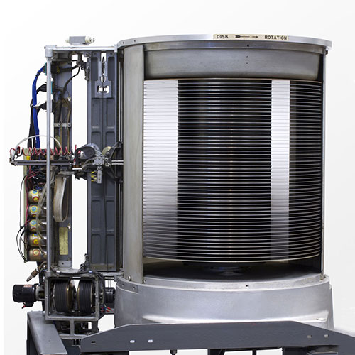 3.75 MB 24″ |
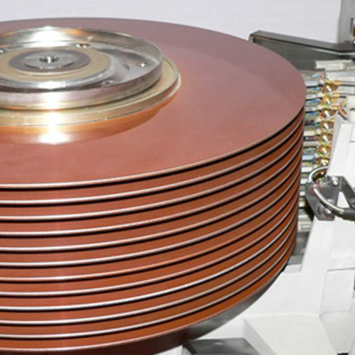 19 MB 24″ |
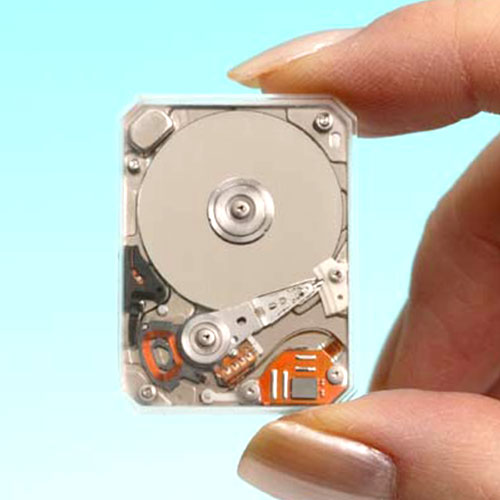 2 GB 0.85″ |
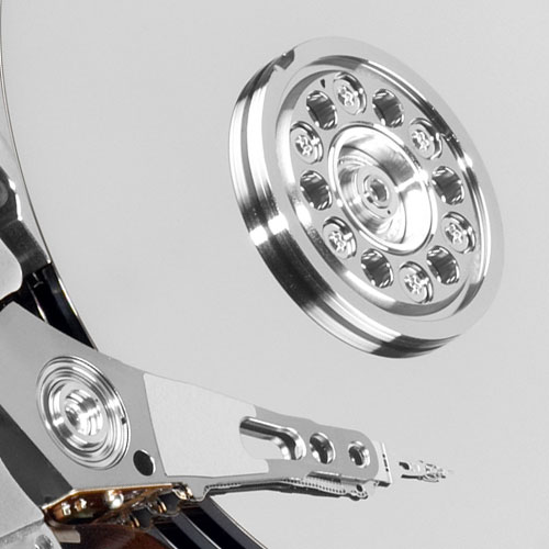 10 TB 3.5″ |
3.75 MB 24″ |
19 MB 24″ |
2 GB 0.85″ |
10 TB 3.5″ |
3.75 MB 24″ |
19 MB 24″ |
2 GB 0.85″ |
10 TB 3.5″ |
3.75 MB 24″ |
19 MB 24″ |
2 GB 0.85″ |
10 TB 3.5″ |
3.75 MB 24″ |
19 MB 24″ |
2 GB 0.85″ |
10 TB 3.5″ |
| Hard Disk: 1956, Reynold Johnson, Educator, was recruited by IBM, then invented a device for storage and retrieval of digital information and with his team, developed and built a range of storage devices that evolved to become the modern hard drive. 24” & 39” PLATTERS: 1958, the IBM350 (24”) with 3.75 MB at 8.8 kB/s: This stationary disk storage unit, the first disk drive, has 50 magnetically coated platters, 610 mm in diameter and 3mm thick. This platter assembly maintained a constant speed of 1,200 RPM and would synchronise a paired of magnetic heads to select a disk then traverse across the platter surface to read and write the individual data blocks. Performance is specified by the average access time required to move the heads to the track, cylinder, sector then read or write data under the head of 100 recording surfaces, each with 100 tracks, this drive, with a total storage capacity of 3.75 MB and achieving a data transfer rate of 8.8 kB/s of non-volatile memory, ensuring stored data is retained when the device is without power. In 1961, the IBM1301 with 20, 24” platters spinning at 1,800 RPM, stored 19 MB at 90 kB/s. At this time, Bryant Computer Products produced one product, the 4000 system with 26, 39” platters with a storage capacity of 205 MB with a data transfer rate of 1.25 MB/s. 14” PLATTERS: In 1962, IBM produced the IBM1311 with 6, 14” platters, package as the first “Disk Pack” with a capacity of 1.02 MB at 156 kB/s. In 1964, the IBM2311 with a disk pack of 6, 14” platters, stored 7.25 MB at 256 kB/s. In 1965, the IBM2314 with a disk pack of 6, 14” platters, stored 14.5 MB at 310 kB/s. 1970, the IBM3330 with a disk pack of 11, 14” platters, stored 100 MB at 806 kB/s. 1973, the IBM3340 with a disk pack of 11, 14” platters, stored 70 MB at 885 kB/s. The IBM, CDC9762 with a disk pack of 5, 14” platters, stored 40 MB at 1.25 MB/s. 1976, the IBM3350 with 8 fixed, 14” platters, stored 317.5 MB at 1.2 MB/s, 1979, the IBM3370 with 7 fixed, 14” platters, stored 571 MB at 1.85 MB/s. The 1980, IBM 3380 with 9 fixed, 14” platters, stored 2.52 GB at 3 MB/s. 11” PLATTERS: In 1993, IBM, IBM3390 with 9 fixed, 11” platters, stored 22 GB at 4.2 MB/s. 8” PLATTERS: In 1980, the IBM62PC with 6, 8” platters, stored 64.5 MB at 1 MB/s. 5.25” PLATTERS: In 1980, Seagate, ST-506 with 5 MB. 1990, IBM0681 with 857 MB. 3.5” PLATTERS: In 1983, Rodime, RO351 with 10 MB. 1991, IBM0663 with 1 GB. 1997, IBM, Deskstar 16GP with 16.8 GB. 2007, Hitachi, Deskstar 7K1000 with 1 TB. 2015, HGST, Ha10 with 10 TB. 2.5” PLATTERS: In 1988, PrairieTek, 220 with 20 MB. 1.8” PLATTERS: In 1991, Integral Peripherals, 1820 with 21.4 MB. 1.3” PLATTERS: In 1992, HP, Kittyhawk with 20 MB. 1” PLATTERS: In 1999, IBM, Microdrive with 340 MB. 0.85” PLATTERS: In 2004, Toshiba, MK2001MTN with 2 GB. The modern form factors are 3½ inch, for desktop computers and 2½ inch, for notebook computers. Interfaces vary with PATA (Parallel ATA), SATA (Serial ATA), SAS (Serial attached SCSI), PCI Express or USB. |
| Hard Disk: 1956, Reynold Johnson, Educator, was recruited by IBM, then invented a device for storage and retrieval of digital information and with his team, developed and built a range of storage devices that evolved to become the modern hard drive. 24” & 39” PLATTERS: 1958, the IBM350 (24”) with 3.75 MB at 8.8 kB/s: This stationary disk storage unit, the first disk drive, has 50 magnetically coated platters, 610 mm in diameter and 3mm thick. This platter assembly maintained a constant speed of 1,200 RPM and would synchronise a paired of magnetic heads to select a disk then traverse across the platter surface to read and write the individual data blocks. Performance is specified by the average access time required to move the heads to the track, cylinder, sector then read or write data under the head of 100 recording surfaces, each with 100 tracks, this drive, with a total storage capacity of 3.75 MB and achieving a data transfer rate of 8.8 kB/s of non-volatile memory, ensuring stored data is retained when the device is without power. In 1961, the IBM1301 with 20, 24” platters spinning at 1,800 RPM, stored 19 MB at 90 kB/s. At this time, Bryant Computer Products produced one product, the 4000 system with 26, 39” platters with a storage capacity of 205 MB with a data transfer rate of 1.25 MB/s. 14” PLATTERS: In 1962, IBM produced the IBM1311 with 6, 14” platters, package as the first “Disk Pack” with a capacity of 1.02 MB at 156 kB/s. In 1964, the IBM2311 with a disk pack of 6, 14” platters, stored 7.25 MB at 256 kB/s. In 1965, the IBM2314 with a disk pack of 6, 14” platters, stored 14.5 MB at 310 kB/s. 1970, the IBM3330 with a disk pack of 11, 14” platters, stored 100 MB at 806 kB/s. 1973, the IBM3340 with a disk pack of 11, 14” platters, stored 70 MB at 885 kB/s. The IBM, CDC9762 with a disk pack of 5, 14” platters, stored 40 MB at 1.25 MB/s. 1976, the IBM3350 with 8 fixed, 14” platters, stored 317.5 MB at 1.2 MB/s, 1979, the IBM3370 with 7 fixed, 14” platters, stored 571 MB at 1.85 MB/s. The 1980, IBM 3380 with 9 fixed, 14” platters, stored 2.52 GB at 3 MB/s. 11” PLATTERS: In 1993, IBM, IBM3390 with 9 fixed, 11” platters, stored 22 GB at 4.2 MB/s. 8” PLATTERS: In 1980, the IBM62PC with 6, 8” platters, stored 64.5 MB at 1 MB/s. 5.25” PLATTERS: In 1980, Seagate, ST-506 with 5 MB. 1990, IBM0681 with 857 MB. 3.5” PLATTERS: In 1983, Rodime, RO351 with 10 MB. 1991, IBM0663 with 1 GB. 1997, IBM, Deskstar 16GP with 16.8 GB. 2007, Hitachi, Deskstar 7K1000 with 1 TB. 2015, HGST, Ha10 with 10 TB. 2.5” PLATTERS: In 1988, PrairieTek, 220 with 20 MB. 1.8” PLATTERS: In 1991, Integral Peripherals, 1820 with 21.4 MB. 1.3” PLATTERS: In 1992, HP, Kittyhawk with 20 MB. 1” PLATTERS: In 1999, IBM, Microdrive with 340 MB. 0.85” PLATTERS: In 2004, Toshiba, MK2001MTN with 2 GB. The modern form factors are 3½ inch, for desktop computers and 2½ inch, for notebook computers. Interfaces vary with PATA (Parallel ATA), SATA (Serial ATA), SAS (Serial attached SCSI), PCI Express or USB. |
| Hard Disk: 1956, Reynold Johnson, Educator, was recruited by IBM, then invented a device for storage and retrieval of digital information and with his team, developed and built a range of storage devices that evolved to become the modern hard drive. 24” & 39” PLATTERS: 1958, the IBM350 (24”) with 3.75 MB at 8.8 kB/s: This stationary disk storage unit, the first disk drive, has 50 magnetically coated platters, 610 mm in diameter and 3mm thick. This platter assembly maintained a constant speed of 1,200 RPM and would synchronise a paired of magnetic heads to select a disk then traverse across the platter surface to read and write the individual data blocks. Performance is specified by the average access time required to move the heads to the track, cylinder, sector then read or write data under the head of 100 recording surfaces, each with 100 tracks, this drive, with a total storage capacity of 3.75 MB and achieving a data transfer rate of 8.8 kB/s of non-volatile memory, ensuring stored data is retained when the device is without power. In 1961, the IBM1301 with 20, 24” platters spinning at 1,800 RPM, stored 19 MB at 90 kB/s. At this time, Bryant Computer Products produced one product, the 4000 system with 26, 39” platters with a storage capacity of 205 MB with a data transfer rate of 1.25 MB/s. 14” PLATTERS: In 1962, IBM produced the IBM1311 with 6, 14” platters, package as the first “Disk Pack” with a capacity of 1.02 MB at 156 kB/s. In 1964, the IBM2311 with a disk pack of 6, 14” platters, stored 7.25 MB at 256 kB/s. In 1965, the IBM2314 with a disk pack of 6, 14” platters, stored 14.5 MB at 310 kB/s. 1970, the IBM3330 with a disk pack of 11, 14” platters, stored 100 MB at 806 kB/s. 1973, the IBM3340 with a disk pack of 11, 14” platters, stored 70 MB at 885 kB/s. The IBM, CDC9762 with a disk pack of 5, 14” platters, stored 40 MB at 1.25 MB/s. 1976, the IBM3350 with 8 fixed, 14” platters, stored 317.5 MB at 1.2 MB/s, 1979, the IBM3370 with 7 fixed, 14” platters, stored 571 MB at 1.85 MB/s. The 1980, IBM 3380 with 9 fixed, 14” platters, stored 2.52 GB at 3 MB/s. 11” PLATTERS: In 1993, IBM, IBM3390 with 9 fixed, 11” platters, stored 22 GB at 4.2 MB/s. 8” PLATTERS: In 1980, the IBM62PC with 6, 8” platters, stored 64.5 MB at 1 MB/s. 5.25” PLATTERS: In 1980, Seagate, ST-506 with 5 MB. 1990, IBM0681 with 857 MB. 3.5” PLATTERS: In 1983, Rodime, RO351 with 10 MB. 1991, IBM0663 with 1 GB. 1997, IBM, Deskstar 16GP with 16.8 GB. 2007, Hitachi, Deskstar 7K1000 with 1 TB. 2015, HGST, Ha10 with 10 TB. 2.5” PLATTERS: In 1988, PrairieTek, 220 with 20 MB. 1.8” PLATTERS: In 1991, Integral Peripherals, 1820 with 21.4 MB. 1.3” PLATTERS: In 1992, HP, Kittyhawk with 20 MB. 1” PLATTERS: In 1999, IBM, Microdrive with 340 MB. 0.85” PLATTERS: In 2004, Toshiba, MK2001MTN with 2 GB. The modern form factors are 3½ inch, for desktop computers and 2½ inch, for notebook computers. Interfaces vary with PATA (Parallel ATA), SATA (Serial ATA), SAS (Serial attached SCSI), PCI Express or USB. |
| Hard Disk: 1956, Reynold Johnson, Educator, was recruited by IBM, then invented a device for storage and retrieval of digital information and with his team, developed and built a range of storage devices that evolved to become the modern hard drive. 24” & 39” PLATTERS: 1958, the IBM350 (24”) with 3.75 MB at 8.8 kB/s: This stationary disk storage unit, the first disk drive, has 50 magnetically coated platters, 610 mm in diameter and 3mm thick. This platter assembly maintained a constant speed of 1,200 RPM and would synchronise a paired of magnetic heads to select a disk then traverse across the platter surface to read and write the individual data blocks. Performance is specified by the average access time required to move the heads to the track, cylinder, sector then read or write data under the head of 100 recording surfaces, each with 100 tracks, this drive, with a total storage capacity of 3.75 MB and achieving a data transfer rate of 8.8 kB/s of non-volatile memory, ensuring stored data is retained when the device is without power. In 1961, the IBM1301 with 20, 24” platters spinning at 1,800 RPM, stored 19 MB at 90 kB/s. At this time, Bryant Computer Products produced one product, the 4000 system with 26, 39” platters with a storage capacity of 205 MB with a data transfer rate of 1.25 MB/s. 14” PLATTERS: In 1962, IBM produced the IBM1311 with 6, 14” platters, package as the first “Disk Pack” with a capacity of 1.02 MB at 156 kB/s. In 1964, the IBM2311 with a disk pack of 6, 14” platters, stored 7.25 MB at 256 kB/s. In 1965, the IBM2314 with a disk pack of 6, 14” platters, stored 14.5 MB at 310 kB/s. 1970, the IBM3330 with a disk pack of 11, 14” platters, stored 100 MB at 806 kB/s. 1973, the IBM3340 with a disk pack of 11, 14” platters, stored 70 MB at 885 kB/s. The IBM, CDC9762 with a disk pack of 5, 14” platters, stored 40 MB at 1.25 MB/s. 1976, the IBM3350 with 8 fixed, 14” platters, stored 317.5 MB at 1.2 MB/s, 1979, the IBM3370 with 7 fixed, 14” platters, stored 571 MB at 1.85 MB/s. The 1980, IBM 3380 with 9 fixed, 14” platters, stored 2.52 GB at 3 MB/s. 11” PLATTERS: In 1993, IBM, IBM3390 with 9 fixed, 11” platters, stored 22 GB at 4.2 MB/s. 8” PLATTERS: In 1980, the IBM62PC with 6, 8” platters, stored 64.5 MB at 1 MB/s. 5.25” PLATTERS: In 1980, Seagate, ST-506 with 5 MB. 1990, IBM0681 with 857 MB. 3.5” PLATTERS: In 1983, Rodime, RO351 with 10 MB. 1991, IBM0663 with 1 GB. 1997, IBM, Deskstar 16GP with 16.8 GB. 2007, Hitachi, Deskstar 7K1000 with 1 TB. 2015, HGST, Ha10 with 10 TB. 2.5” PLATTERS: In 1988, PrairieTek, 220 with 20 MB. 1.8” PLATTERS: In 1991, Integral Peripherals, 1820 with 21.4 MB. 1.3” PLATTERS: In 1992, HP, Kittyhawk with 20 MB. 1” PLATTERS: In 1999, IBM, Microdrive with 340 MB. 0.85” PLATTERS: In 2004, Toshiba, MK2001MTN with 2 GB. The modern form factors are 3½ inch, for desktop computers and 2½ inch, for notebook computers. Interfaces vary with PATA (Parallel ATA), SATA (Serial ATA), SAS (Serial attached SCSI), PCI Express or USB. |
| Hard Disk: 1956, Reynold Johnson, Educator, was recruited by IBM, then invented a device for storage and retrieval of digital information and with his team, developed and built a range of storage devices that evolved to become the modern hard drive. 24” & 39” PLATTERS: 1958, the IBM350 (24”) with 3.75 MB at 8.8 kB/s: This stationary disk storage unit, the first disk drive, has 50 magnetically coated platters, 610 mm in diameter and 3mm thick. This platter assembly maintained a constant speed of 1,200 RPM and would synchronise a paired of magnetic heads to select a disk then traverse across the platter surface to read and write the individual data blocks. Performance is specified by the average access time required to move the heads to the track, cylinder, sector then read or write data under the head of 100 recording surfaces, each with 100 tracks, this drive, with a total storage capacity of 3.75 MB and achieving a data transfer rate of 8.8 kB/s of non-volatile memory, ensuring stored data is retained when the device is without power. In 1961, the IBM1301 with 20, 24” platters spinning at 1,800 RPM, stored 19 MB at 90 kB/s. At this time, Bryant Computer Products produced one product, the 4000 system with 26, 39” platters with a storage capacity of 205 MB with a data transfer rate of 1.25 MB/s. 14” PLATTERS: In 1962, IBM produced the IBM1311 with 6, 14” platters, package as the first “Disk Pack” with a capacity of 1.02 MB at 156 kB/s. In 1964, the IBM2311 with a disk pack of 6, 14” platters, stored 7.25 MB at 256 kB/s. In 1965, the IBM2314 with a disk pack of 6, 14” platters, stored 14.5 MB at 310 kB/s. 1970, the IBM3330 with a disk pack of 11, 14” platters, stored 100 MB at 806 kB/s. 1973, the IBM3340 with a disk pack of 11, 14” platters, stored 70 MB at 885 kB/s. The IBM, CDC9762 with a disk pack of 5, 14” platters, stored 40 MB at 1.25 MB/s. 1976, the IBM3350 with 8 fixed, 14” platters, stored 317.5 MB at 1.2 MB/s, 1979, the IBM3370 with 7 fixed, 14” platters, stored 571 MB at 1.85 MB/s. The 1980, IBM 3380 with 9 fixed, 14” platters, stored 2.52 GB at 3 MB/s. 11” PLATTERS: In 1993, IBM, IBM3390 with 9 fixed, 11” platters, stored 22 GB at 4.2 MB/s. 8” PLATTERS: In 1980, the IBM62PC with 6, 8” platters, stored 64.5 MB at 1 MB/s. 5.25” PLATTERS: In 1980, Seagate, ST-506 with 5 MB. 1990, IBM0681 with 857 MB. 3.5” PLATTERS: In 1983, Rodime, RO351 with 10 MB. 1991, IBM0663 with 1 GB. 1997, IBM, Deskstar 16GP with 16.8 GB. 2007, Hitachi, Deskstar 7K1000 with 1 TB. 2015, HGST, Ha10 with 10 TB. 2.5” PLATTERS: In 1988, PrairieTek, 220 with 20 MB. 1.8” PLATTERS: In 1991, Integral Peripherals, 1820 with 21.4 MB. 1.3” PLATTERS: In 1992, HP, Kittyhawk with 20 MB. 1” PLATTERS: In 1999, IBM, Microdrive with 340 MB. 0.85” PLATTERS: In 2004, Toshiba, MK2001MTN with 2 GB. The modern form factors are 3½ inch, for desktop computers and 2½ inch, for notebook computers. Interfaces vary with PATA (Parallel ATA), SATA (Serial ATA), SAS (Serial attached SCSI), PCI Express or USB. |
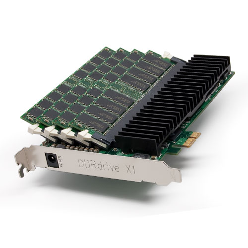 16 MB SSD |
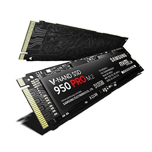 512 GB SSD |
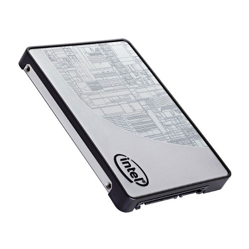 1 TB SSD |
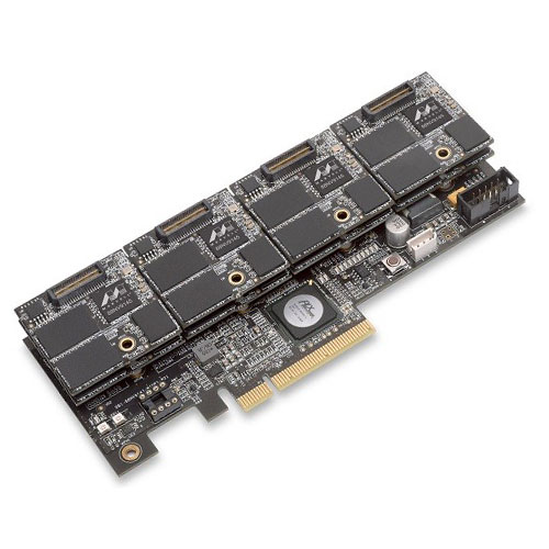 16 TB SSD |
16 MB SSD |
512 GB SSD |
1 TB SSD |
16 TB SSD |
16 MB SSD |
512 GB SSD |
1 TB SSD |
16 TB SSD |
16 MB SSD |
512 GB SSD |
1 TB SSD |
16 TB SSD |
16 MB SSD |
512 GB SSD |
1 TB SSD |
16 TB SSD |
| Solid State Drive: This storage device utilises integrated non-volatile NAND-based flash memory circuits to store data. They are designed as a direct replacement for traditional drives with a dramatic increase in performance, or capitalise upon drivers specifically developed with new I/O interfaces, like SATA Express. As an SSD has no moving components, they are resistant to physical shock, run silently and on less power. An SSD may also be made from volatile “Cache” and/or “Primary” Random Access Memory (RAM) for extreme performance and do require a battery backup to maintain storage. Hybrid drives are a combination of SSD and Traditional HDD, RAM, ROM, EEPROM, ORGANIC, QUANTUM or combination thereof. Solid State Drives date back to the Magnetic Core Memory of 1951and the Charged Capacitor Read Only Score (CCROS) Memory of 1966. In 1976, SSD by Dataram, Bulk Core of 2 MB in capacity, emulated a DEC hard disk with a chassis that held 8x 256k x 18 RAM modules. In 1977, the Micro Memory, MM-S100, an 8 KB, non-volatile RAM card based on magnetic core store with compatibility of Intel’s 8080 microprocessor. 1978, Texas Memory Systems produced the TMS16K, a 16 KB RAM-based SSD, designed to accelerate field seismic data acquisition for oil companies. 1982, SemiDisk Systems produced the S-100, a 512 KB RAM-based SSD accelerator for the Intel microprocessor. The Sharp PC-5000, in 1983, used an SSD cartridge containing 128 kB of bubble memory. In 1984, Tallgrass Technologies Corporation built a tape backup unit of 40 MB with a 20 MB SSD built in and used as a bootable hard drive. 1986, the Santa Clara Systems created the BatRam, a 20 MB mass storage system with battery backup. In 1990, SunDisk (now SanDisk) created a prototype solid state disk (SSD) with 4 MB of non-volatile flash memory, which was presented to IBM for evaluation. In 1994, CERAM created the T8000, an 80 MB 10MP/s SSD with the ability to chain multiple slots to appear as a single SSD of up to 960 MB. In that same year, Texas Memory Systems built the SAM-2000, an 8 GB SSD with 500MB/s internal bandwidth. In 1995, M-Systems created the DiskOnChip, a 32 MB SSD with TrueFFS, software that made the computer see Flash memory as a disk drive. 1996, ATTO Technology built the SiliconDisk II, a 1.6 GB, RAM SSD with 5.25” form factor, SCSI-3 interface and a throughput of 80MB/s. In 1999, BiTMICRO released an 18 GB 3.5” SSD. In 2007, Fusion-IO produced a 320 GB, PCI Express based SSD with 100,000 input/output operations per second (IOPS). 2009, OCZ Technology created a 1 TB Flash SSD using PCI Express ×8 interface, achieving a maximum write speed of 654 MB/s and maximum read speed of 712 MB/s. With the same year, the OCZ RevoDrive X2 PCI Express SSD of 960 GB with 740 MB/s sequential speeds and random small file writes of up to 120,000 IOPS. In 2010, Fusion-IO released ioDrive Octal, an SSD utilising the PCIe x16 Gen 2.0 interface with 5.12 TB storage, 6.0 GB/s read speed, 4.4 GB/s write speed and latency of 30 microseconds. In 2015, OCZ Technology creates the Z-Drive R5 CloudServ 16 TB SSD utilising the PCIe x16 Gen 3.0 interface with transfer speeds of 7.2 GB/s and 2.52 million IOPS. |
| Solid State Drive: This storage device utilises integrated non-volatile NAND-based flash memory circuits to store data. They are designed as a direct replacement for traditional drives with a dramatic increase in performance, or capitalise upon drivers specifically developed with new I/O interfaces, like SATA Express. As an SSD has no moving components, they are resistant to physical shock, run silently and on less power. An SSD may also be made from volatile “Cache” and/or “Primary” Random Access Memory (RAM) for extreme performance and do require a battery backup to maintain storage. Hybrid drives are a combination of SSD and Traditional HDD, RAM, ROM, EEPROM, ORGANIC, QUANTUM or combination thereof. Solid State Drives date back to the Magnetic Core Memory of 1951and the Charged Capacitor Read Only Score (CCROS) Memory of 1966. In 1976, SSD by Dataram, Bulk Core of 2 MB in capacity, emulated a DEC hard disk with a chassis that held 8x 256k x 18 RAM modules. In 1977, the Micro Memory, MM-S100, an 8 KB, non-volatile RAM card based on magnetic core store with compatibility of Intel’s 8080 microprocessor. 1978, Texas Memory Systems produced the TMS16K, a 16 KB RAM-based SSD, designed to accelerate field seismic data acquisition for oil companies. 1982, SemiDisk Systems produced the S-100, a 512 KB RAM-based SSD accelerator for the Intel microprocessor. The Sharp PC-5000, in 1983, used an SSD cartridge containing 128 kB of bubble memory. In 1984, Tallgrass Technologies Corporation built a tape backup unit of 40 MB with a 20 MB SSD built in and used as a bootable hard drive. 1986, the Santa Clara Systems created the BatRam, a 20 MB mass storage system with battery backup. In 1990, SunDisk (now SanDisk) created a prototype solid state disk (SSD) with 4 MB of non-volatile flash memory, which was presented to IBM for evaluation. In 1994, CERAM created the T8000, an 80 MB 10MP/s SSD with the ability to chain multiple slots to appear as a single SSD of up to 960 MB. In that same year, Texas Memory Systems built the SAM-2000, an 8 GB SSD with 500MB/s internal bandwidth. In 1995, M-Systems created the DiskOnChip, a 32 MB SSD with TrueFFS, software that made the computer see Flash memory as a disk drive. 1996, ATTO Technology built the SiliconDisk II, a 1.6 GB, RAM SSD with 5.25” form factor, SCSI-3 interface and a throughput of 80MB/s. In 1999, BiTMICRO released an 18 GB 3.5” SSD. In 2007, Fusion-IO produced a 320 GB, PCI Express based SSD with 100,000 input/output operations per second (IOPS). 2009, OCZ Technology created a 1 TB Flash SSD using PCI Express ×8 interface, achieving a maximum write speed of 654 MB/s and maximum read speed of 712 MB/s. With the same year, the OCZ RevoDrive X2 PCI Express SSD of 960 GB with 740 MB/s sequential speeds and random small file writes of up to 120,000 IOPS. In 2010, Fusion-IO released ioDrive Octal, an SSD utilising the PCIe x16 Gen 2.0 interface with 5.12 TB storage, 6.0 GB/s read speed, 4.4 GB/s write speed and latency of 30 microseconds. In 2015, OCZ Technology creates the Z-Drive R5 CloudServ 16 TB SSD utilising the PCIe x16 Gen 3.0 interface with transfer speeds of 7.2 GB/s and 2.52 million IOPS. |
| Solid State Drive: This storage device utilises integrated non-volatile NAND-based flash memory circuits to store data. They are designed as a direct replacement for traditional drives with a dramatic increase in performance, or capitalise upon drivers specifically developed with new I/O interfaces, like SATA Express. As an SSD has no moving components, they are resistant to physical shock, run silently and on less power. An SSD may also be made from volatile “Cache” and/or “Primary” Random Access Memory (RAM) for extreme performance and do require a battery backup to maintain storage. Hybrid drives are a combination of SSD and Traditional HDD, RAM, ROM, EEPROM, ORGANIC, QUANTUM or combination thereof. Solid State Drives date back to the Magnetic Core Memory of 1951and the Charged Capacitor Read Only Score (CCROS) Memory of 1966. In 1976, SSD by Dataram, Bulk Core of 2 MB in capacity, emulated a DEC hard disk with a chassis that held 8x 256k x 18 RAM modules. In 1977, the Micro Memory, MM-S100, an 8 KB, non-volatile RAM card based on magnetic core store with compatibility of Intel’s 8080 microprocessor. 1978, Texas Memory Systems produced the TMS16K, a 16 KB RAM-based SSD, designed to accelerate field seismic data acquisition for oil companies. 1982, SemiDisk Systems produced the S-100, a 512 KB RAM-based SSD accelerator for the Intel microprocessor. The Sharp PC-5000, in 1983, used an SSD cartridge containing 128 kB of bubble memory. In 1984, Tallgrass Technologies Corporation built a tape backup unit of 40 MB with a 20 MB SSD built in and used as a bootable hard drive. 1986, the Santa Clara Systems created the BatRam, a 20 MB mass storage system with battery backup. In 1990, SunDisk (now SanDisk) created a prototype solid state disk (SSD) with 4 MB of non-volatile flash memory, which was presented to IBM for evaluation. In 1994, CERAM created the T8000, an 80 MB 10MP/s SSD with the ability to chain multiple slots to appear as a single SSD of up to 960 MB. In that same year, Texas Memory Systems built the SAM-2000, an 8 GB SSD with 500MB/s internal bandwidth. In 1995, M-Systems created the DiskOnChip, a 32 MB SSD with TrueFFS, software that made the computer see Flash memory as a disk drive. 1996, ATTO Technology built the SiliconDisk II, a 1.6 GB, RAM SSD with 5.25” form factor, SCSI-3 interface and a throughput of 80MB/s. In 1999, BiTMICRO released an 18 GB 3.5” SSD. In 2007, Fusion-IO produced a 320 GB, PCI Express based SSD with 100,000 input/output operations per second (IOPS). 2009, OCZ Technology created a 1 TB Flash SSD using PCI Express ×8 interface, achieving a maximum write speed of 654 MB/s and maximum read speed of 712 MB/s. With the same year, the OCZ RevoDrive X2 PCI Express SSD of 960 GB with 740 MB/s sequential speeds and random small file writes of up to 120,000 IOPS. In 2010, Fusion-IO released ioDrive Octal, an SSD utilising the PCIe x16 Gen 2.0 interface with 5.12 TB storage, 6.0 GB/s read speed, 4.4 GB/s write speed and latency of 30 microseconds. In 2015, OCZ Technology creates the Z-Drive R5 CloudServ 16 TB SSD utilising the PCIe x16 Gen 3.0 interface with transfer speeds of 7.2 GB/s and 2.52 million IOPS. |
| Solid State Drive: This storage device utilises integrated non-volatile NAND-based flash memory circuits to store data. They are designed as a direct replacement for traditional drives with a dramatic increase in performance, or capitalise upon drivers specifically developed with new I/O interfaces, like SATA Express. As an SSD has no moving components, they are resistant to physical shock, run silently and on less power. An SSD may also be made from volatile “Cache” and/or “Primary” Random Access Memory (RAM) for extreme performance and do require a battery backup to maintain storage. Hybrid drives are a combination of SSD and Traditional HDD, RAM, ROM, EEPROM, ORGANIC, QUANTUM or combination thereof. Solid State Drives date back to the Magnetic Core Memory of 1951and the Charged Capacitor Read Only Score (CCROS) Memory of 1966. In 1976, SSD by Dataram, Bulk Core of 2 MB in capacity, emulated a DEC hard disk with a chassis that held 8x 256k x 18 RAM modules. In 1977, the Micro Memory, MM-S100, an 8 KB, non-volatile RAM card based on magnetic core store with compatibility of Intel’s 8080 microprocessor. 1978, Texas Memory Systems produced the TMS16K, a 16 KB RAM-based SSD, designed to accelerate field seismic data acquisition for oil companies. 1982, SemiDisk Systems produced the S-100, a 512 KB RAM-based SSD accelerator for the Intel microprocessor. The Sharp PC-5000, in 1983, used an SSD cartridge containing 128 kB of bubble memory. In 1984, Tallgrass Technologies Corporation built a tape backup unit of 40 MB with a 20 MB SSD built in and used as a bootable hard drive. 1986, the Santa Clara Systems created the BatRam, a 20 MB mass storage system with battery backup. In 1990, SunDisk (now SanDisk) created a prototype solid state disk (SSD) with 4 MB of non-volatile flash memory, which was presented to IBM for evaluation. In 1994, CERAM created the T8000, an 80 MB 10MP/s SSD with the ability to chain multiple slots to appear as a single SSD of up to 960 MB. In that same year, Texas Memory Systems built the SAM-2000, an 8 GB SSD with 500MB/s internal bandwidth. In 1995, M-Systems created the DiskOnChip, a 32 MB SSD with TrueFFS, software that made the computer see Flash memory as a disk drive. 1996, ATTO Technology built the SiliconDisk II, a 1.6 GB, RAM SSD with 5.25” form factor, SCSI-3 interface and a throughput of 80MB/s. In 1999, BiTMICRO released an 18 GB 3.5” SSD. In 2007, Fusion-IO produced a 320 GB, PCI Express based SSD with 100,000 input/output operations per second (IOPS). 2009, OCZ Technology created a 1 TB Flash SSD using PCI Express ×8 interface, achieving a maximum write speed of 654 MB/s and maximum read speed of 712 MB/s. With the same year, the OCZ RevoDrive X2 PCI Express SSD of 960 GB with 740 MB/s sequential speeds and random small file writes of up to 120,000 IOPS. In 2010, Fusion-IO released ioDrive Octal, an SSD utilising the PCIe x16 Gen 2.0 interface with 5.12 TB storage, 6.0 GB/s read speed, 4.4 GB/s write speed and latency of 30 microseconds. In 2015, OCZ Technology creates the Z-Drive R5 CloudServ 16 TB SSD utilising the PCIe x16 Gen 3.0 interface with transfer speeds of 7.2 GB/s and 2.52 million IOPS. |
| Solid State Drive: This storage device utilises integrated non-volatile NAND-based flash memory circuits to store data. They are designed as a direct replacement for traditional drives with a dramatic increase in performance, or capitalise upon drivers specifically developed with new I/O interfaces, like SATA Express. As an SSD has no moving components, they are resistant to physical shock, run silently and on less power. An SSD may also be made from volatile “Cache” and/or “Primary” Random Access Memory (RAM) for extreme performance and do require a battery backup to maintain storage. Hybrid drives are a combination of SSD and Traditional HDD, RAM, ROM, EEPROM, ORGANIC, QUANTUM or combination thereof. Solid State Drives date back to the Magnetic Core Memory of 1951and the Charged Capacitor Read Only Score (CCROS) Memory of 1966. In 1976, SSD by Dataram, Bulk Core of 2 MB in capacity, emulated a DEC hard disk with a chassis that held 8x 256k x 18 RAM modules. In 1977, the Micro Memory, MM-S100, an 8 KB, non-volatile RAM card based on magnetic core store with compatibility of Intel’s 8080 microprocessor. 1978, Texas Memory Systems produced the TMS16K, a 16 KB RAM-based SSD, designed to accelerate field seismic data acquisition for oil companies. 1982, SemiDisk Systems produced the S-100, a 512 KB RAM-based SSD accelerator for the Intel microprocessor. The Sharp PC-5000, in 1983, used an SSD cartridge containing 128 kB of bubble memory. In 1984, Tallgrass Technologies Corporation built a tape backup unit of 40 MB with a 20 MB SSD built in and used as a bootable hard drive. 1986, the Santa Clara Systems created the BatRam, a 20 MB mass storage system with battery backup. In 1990, SunDisk (now SanDisk) created a prototype solid state disk (SSD) with 4 MB of non-volatile flash memory, which was presented to IBM for evaluation. In 1994, CERAM created the T8000, an 80 MB 10MP/s SSD with the ability to chain multiple slots to appear as a single SSD of up to 960 MB. In that same year, Texas Memory Systems built the SAM-2000, an 8 GB SSD with 500MB/s internal bandwidth. In 1995, M-Systems created the DiskOnChip, a 32 MB SSD with TrueFFS, software that made the computer see Flash memory as a disk drive. 1996, ATTO Technology built the SiliconDisk II, a 1.6 GB, RAM SSD with 5.25” form factor, SCSI-3 interface and a throughput of 80MB/s. In 1999, BiTMICRO released an 18 GB 3.5” SSD. In 2007, Fusion-IO produced a 320 GB, PCI Express based SSD with 100,000 input/output operations per second (IOPS). 2009, OCZ Technology created a 1 TB Flash SSD using PCI Express ×8 interface, achieving a maximum write speed of 654 MB/s and maximum read speed of 712 MB/s. With the same year, the OCZ RevoDrive X2 PCI Express SSD of 960 GB with 740 MB/s sequential speeds and random small file writes of up to 120,000 IOPS. In 2010, Fusion-IO released ioDrive Octal, an SSD utilising the PCIe x16 Gen 2.0 interface with 5.12 TB storage, 6.0 GB/s read speed, 4.4 GB/s write speed and latency of 30 microseconds. In 2015, OCZ Technology creates the Z-Drive R5 CloudServ 16 TB SSD utilising the PCIe x16 Gen 3.0 interface with transfer speeds of 7.2 GB/s and 2.52 million IOPS. |
 |
|
|
|
|
| Definition: Tertiary storage is divided into three main areas: “Online” is the immediate connection to addressable memory on a remote device, as with a network drive or cloud service. “Nearline” is physically isolated storage that requires one command to be online, as with a robotic mechanism to mount and dismount removable storage media. “Offline” requires human intervention to become online, as with removable media. In 1962, the network for the Advanced Research Projects Agency of the United States Department of Defence created ARPANET, which created the early packet switching network and implemented the use of the TCP/IP protocol, which became the internet. Cloud storage is stored in logical pools with the physical storage spanning across multiple servers, locations and managed by a host. Tertiary storage is accessed through an application programming interface (API). Cloud network service providers are: CompuServe (1983), AT&T (1994), Akamai for Apple, Facebook, Bing, Twitter and eBay (1998), SmugMug (2002), Amazon (2006), Dropbox (2007), Microsoft (2008), Cloudera (2008), Google (2010), Pinterest (2010), Synaptop (2011), Adobe (2012). |
| Definition: Tertiary storage is divided into three main areas: “Online” is the immediate connection to addressable memory on a remote device, as with a network drive or cloud service. “Nearline” is physically isolated storage that requires one command to be online, as with a robotic mechanism to mount and dismount removable storage media. “Offline” requires human intervention to become online, as with removable media. In 1962, the network for the Advanced Research Projects Agency of the United States Department of Defence created ARPANET, which created the early packet switching network and implemented the use of the TCP/IP protocol, which became the internet. Cloud storage is stored in logical pools with the physical storage spanning across multiple servers, locations and managed by a host. Tertiary storage is accessed through an application programming interface (API). Cloud network service providers are: CompuServe (1983), AT&T (1994), Akamai for Apple, Facebook, Bing, Twitter and eBay (1998), SmugMug (2002), Amazon (2006), Dropbox (2007), Microsoft (2008), Cloudera (2008), Google (2010), Pinterest (2010), Synaptop (2011), Adobe (2012). |
| Definition: Tertiary storage is divided into three main areas: “Online” is the immediate connection to addressable memory on a remote device, as with a network drive or cloud service. “Nearline” is physically isolated storage that requires one command to be online, as with a robotic mechanism to mount and dismount removable storage media. “Offline” requires human intervention to become online, as with removable media. In 1962, the network for the Advanced Research Projects Agency of the United States Department of Defence created ARPANET, which created the early packet switching network and implemented the use of the TCP/IP protocol, which became the internet. Cloud storage is stored in logical pools with the physical storage spanning across multiple servers, locations and managed by a host. Tertiary storage is accessed through an application programming interface (API). Cloud network service providers are: CompuServe (1983), AT&T (1994), Akamai for Apple, Facebook, Bing, Twitter and eBay (1998), SmugMug (2002), Amazon (2006), Dropbox (2007), Microsoft (2008), Cloudera (2008), Google (2010), Pinterest (2010), Synaptop (2011), Adobe (2012). |
| Definition: Tertiary storage is divided into three main areas: “Online” is the immediate connection to addressable memory on a remote device, as with a network drive or cloud service. “Nearline” is physically isolated storage that requires one command to be online, as with a robotic mechanism to mount and dismount removable storage media. “Offline” requires human intervention to become online, as with removable media. In 1962, the network for the Advanced Research Projects Agency of the United States Department of Defence created ARPANET, which created the early packet switching network and implemented the use of the TCP/IP protocol, which became the internet. Cloud storage is stored in logical pools with the physical storage spanning across multiple servers, locations and managed by a host. Tertiary storage is accessed through an application programming interface (API). Cloud network service providers are: CompuServe (1983), AT&T (1994), Akamai for Apple, Facebook, Bing, Twitter and eBay (1998), SmugMug (2002), Amazon (2006), Dropbox (2007), Microsoft (2008), Cloudera (2008), Google (2010), Pinterest (2010), Synaptop (2011), Adobe (2012). |
| Definition: Tertiary storage is divided into three main areas: “Online” is the immediate connection to addressable memory on a remote device, as with a network drive or cloud service. “Nearline” is physically isolated storage that requires one command to be online, as with a robotic mechanism to mount and dismount removable storage media. “Offline” requires human intervention to become online, as with removable media. In 1962, the network for the Advanced Research Projects Agency of the United States Department of Defence created ARPANET, which created the early packet switching network and implemented the use of the TCP/IP protocol, which became the internet. Cloud storage is stored in logical pools with the physical storage spanning across multiple servers, locations and managed by a host. Tertiary storage is accessed through an application programming interface (API). Cloud network service providers are: CompuServe (1983), AT&T (1994), Akamai for Apple, Facebook, Bing, Twitter and eBay (1998), SmugMug (2002), Amazon (2006), Dropbox (2007), Microsoft (2008), Cloudera (2008), Google (2010), Pinterest (2010), Synaptop (2011), Adobe (2012). |
 Network Memory |
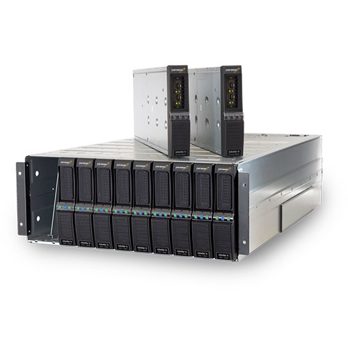 Network Storage |
 IBM Z13 |
 Server Farm |
Network Memory |
Network Storage |
IBM Z13 |
Server Farm |
Network Memory |
Network Storage |
IBM Z13 |
Server Farm |
Network Memory |
Network Storage |
IBM Z13 |
Server Farm |
Network Memory |
Network Storage |
IBM Z13 |
Server Farm |
| Invented in 1963 by Joseph Licklider. |
| Invented in 1963 by Joseph Licklider. |
| Invented in 1963 by Joseph Licklider. |
| Invented in 1963 by Joseph Licklider. |
| Invented in 1963 by Joseph Licklider. |
 |
|
|
|
|
| Definition: In 1980, 3 engineers from IBM Research, created affordable, commercial VRAM for graphics adapters and in 1986, the PC/RT system from IBM would be the first to implemented this new standard for graphics. VRAM, dual-ported memory improved the overall framebuffer throughput which enabled high-resolution, high-speed, colour graphics. VRAM has two sets of data outputs that are used simultaneously. The first DRAM port, is addressed in a similar manner to traditional DRAM. The second port, provides a read-only video output, providing a high throughput, serial data channel for the graphic chipset. VRAM, described as “All points addressable raster display memory”, operates through a controller that instruct the DRAM port to select a memory array row to be displayed, instructs the VRAM to copy the row to a shift register, which is an internal row-buffer. The controller then continues use of the DRAM port, whilst the controller feeds a shift clock (SCLK) to the VRAM’s video port. Every SCLK pulse instruct the VRAM to deliver the next data bit, in strict address order, from the shift register to the video port. This form of VRAM with internal, on-chip buffering imposed a standard and established a new platform to develop from. WRAM, was a step improvement by supporting greater bandwidth than VRAM and optimising common text drawing and block fill operations. Multibank DRAM (MDRAM), interleaves main memory with second-level cache memory and splits its memory capacity into blocks of 256 kB. This allowed for instructions to two different banks in a single clock cycle and provided the optimal RAM memory size of 2.25 MB, for 24-bit colour at a resolution of 1024×768. Synchronous Graphics RAM (SGRAM) functions by writing to a bit plane exclusively (bit masking) and filling a memory block with a colour (block write). Although SGRAM is single-ported, two memory pages open simultaneously, replicating the dual-port nature of other video RAM. Graphics Double Data Rate Memory, GDDR is Synchronous, Dynamic Random Access Memory, SDRAM and is specifically designed for video graphics with high band width. Graphics Double Data Rate Memory, DDR is Synchronous, Dynamic Random Access Memory, SDRAM: GDDR1 RAM of 1.2 GB/s, GDDR2 RAM of 6.2 GB/s, GDDR3 RAM of 10 GB/s, GDDR4 RAM of 14 GB/s, GDDR5 RAM of 28 GB/s to the latest stacked 3D DRAM memory, XPOINT, MCDRAM, High Bandwidth Memory (HBM) of 128 GB/s. |
| Definition: In 1980, 3 engineers from IBM Research, created affordable, commercial VRAM for graphics adapters and in 1986, the PC/RT system from IBM would be the first to implemented this new standard for graphics. VRAM, dual-ported memory improved the overall framebuffer throughput which enabled high-resolution, high-speed, colour graphics. VRAM has two sets of data outputs that are used simultaneously. The first DRAM port, is addressed in a similar manner to traditional DRAM. The second port, provides a read-only video output, providing a high throughput, serial data channel for the graphic chipset. VRAM, described as “All points addressable raster display memory”, operates through a controller that instruct the DRAM port to select a memory array row to be displayed, instructs the VRAM to copy the row to a shift register, which is an internal row-buffer. The controller then continues use of the DRAM port, whilst the controller feeds a shift clock (SCLK) to the VRAM’s video port. Every SCLK pulse instruct the VRAM to deliver the next data bit, in strict address order, from the shift register to the video port. This form of VRAM with internal, on-chip buffering imposed a standard and established a new platform to develop from. WRAM, was a step improvement by supporting greater bandwidth than VRAM and optimising common text drawing and block fill operations. Multibank DRAM (MDRAM), interleaves main memory with second-level cache memory and splits its memory capacity into blocks of 256 kB. This allowed for instructions to two different banks in a single clock cycle and provided the optimal RAM memory size of 2.25 MB, for 24-bit colour at a resolution of 1024×768. Synchronous Graphics RAM (SGRAM) functions by writing to a bit plane exclusively (bit masking) and filling a memory block with a colour (block write). Although SGRAM is single-ported, two memory pages open simultaneously, replicating the dual-port nature of other video RAM. Graphics Double Data Rate Memory, GDDR is Synchronous, Dynamic Random Access Memory, SDRAM and is specifically designed for video graphics with high band width. Graphics Double Data Rate Memory, DDR is Synchronous, Dynamic Random Access Memory, SDRAM: GDDR1 RAM of 1.2 GB/s, GDDR2 RAM of 6.2 GB/s, GDDR3 RAM of 10 GB/s, GDDR4 RAM of 14 GB/s, GDDR5 RAM of 28 GB/s to the latest stacked 3D DRAM memory, XPOINT, MCDRAM, High Bandwidth Memory (HBM) of 128 GB/s. |
| Definition: In 1980, 3 engineers from IBM Research, created affordable, commercial VRAM for graphics adapters and in 1986, the PC/RT system from IBM would be the first to implemented this new standard for graphics. VRAM, dual-ported memory improved the overall framebuffer throughput which enabled high-resolution, high-speed, colour graphics. VRAM has two sets of data outputs that are used simultaneously. The first DRAM port, is addressed in a similar manner to traditional DRAM. The second port, provides a read-only video output, providing a high throughput, serial data channel for the graphic chipset. VRAM, described as “All points addressable raster display memory”, operates through a controller that instruct the DRAM port to select a memory array row to be displayed, instructs the VRAM to copy the row to a shift register, which is an internal row-buffer. The controller then continues use of the DRAM port, whilst the controller feeds a shift clock (SCLK) to the VRAM’s video port. Every SCLK pulse instruct the VRAM to deliver the next data bit, in strict address order, from the shift register to the video port. This form of VRAM with internal, on-chip buffering imposed a standard and established a new platform to develop from. WRAM, was a step improvement by supporting greater bandwidth than VRAM and optimising common text drawing and block fill operations. Multibank DRAM (MDRAM), interleaves main memory with second-level cache memory and splits its memory capacity into blocks of 256 kB. This allowed for instructions to two different banks in a single clock cycle and provided the optimal RAM memory size of 2.25 MB, for 24-bit colour at a resolution of 1024×768. Synchronous Graphics RAM (SGRAM) functions by writing to a bit plane exclusively (bit masking) and filling a memory block with a colour (block write). Although SGRAM is single-ported, two memory pages open simultaneously, replicating the dual-port nature of other video RAM. Graphics Double Data Rate Memory, GDDR is Synchronous, Dynamic Random Access Memory, SDRAM and is specifically designed for video graphics with high band width. Graphics Double Data Rate Memory, DDR is Synchronous, Dynamic Random Access Memory, SDRAM: GDDR1 RAM of 1.2 GB/s, GDDR2 RAM of 6.2 GB/s, GDDR3 RAM of 10 GB/s, GDDR4 RAM of 14 GB/s, GDDR5 RAM of 28 GB/s to the latest stacked 3D DRAM memory, XPOINT, MCDRAM, High Bandwidth Memory (HBM) of 128 GB/s. |
| Definition: In 1980, 3 engineers from IBM Research, created affordable, commercial VRAM for graphics adapters and in 1986, the PC/RT system from IBM would be the first to implemented this new standard for graphics. VRAM, dual-ported memory improved the overall framebuffer throughput which enabled high-resolution, high-speed, colour graphics. VRAM has two sets of data outputs that are used simultaneously. The first DRAM port, is addressed in a similar manner to traditional DRAM. The second port, provides a read-only video output, providing a high throughput, serial data channel for the graphic chipset. VRAM, described as “All points addressable raster display memory”, operates through a controller that instruct the DRAM port to select a memory array row to be displayed, instructs the VRAM to copy the row to a shift register, which is an internal row-buffer. The controller then continues use of the DRAM port, whilst the controller feeds a shift clock (SCLK) to the VRAM’s video port. Every SCLK pulse instruct the VRAM to deliver the next data bit, in strict address order, from the shift register to the video port. This form of VRAM with internal, on-chip buffering imposed a standard and established a new platform to develop from. WRAM, was a step improvement by supporting greater bandwidth than VRAM and optimising common text drawing and block fill operations. Multibank DRAM (MDRAM), interleaves main memory with second-level cache memory and splits its memory capacity into blocks of 256 kB. This allowed for instructions to two different banks in a single clock cycle and provided the optimal RAM memory size of 2.25 MB, for 24-bit colour at a resolution of 1024×768. Synchronous Graphics RAM (SGRAM) functions by writing to a bit plane exclusively (bit masking) and filling a memory block with a colour (block write). Although SGRAM is single-ported, two memory pages open simultaneously, replicating the dual-port nature of other video RAM. Graphics Double Data Rate Memory, GDDR is Synchronous, Dynamic Random Access Memory, SDRAM and is specifically designed for video graphics with high band width. Graphics Double Data Rate Memory, DDR is Synchronous, Dynamic Random Access Memory, SDRAM: GDDR1 RAM of 1.2 GB/s, GDDR2 RAM of 6.2 GB/s, GDDR3 RAM of 10 GB/s, GDDR4 RAM of 14 GB/s, GDDR5 RAM of 28 GB/s to the latest stacked 3D DRAM memory, XPOINT, MCDRAM, High Bandwidth Memory (HBM) of 128 GB/s. |
| Definition: In 1980, 3 engineers from IBM Research, created affordable, commercial VRAM for graphics adapters and in 1986, the PC/RT system from IBM would be the first to implemented this new standard for graphics. VRAM, dual-ported memory improved the overall framebuffer throughput which enabled high-resolution, high-speed, colour graphics. VRAM has two sets of data outputs that are used simultaneously. The first DRAM port, is addressed in a similar manner to traditional DRAM. The second port, provides a read-only video output, providing a high throughput, serial data channel for the graphic chipset. VRAM, described as “All points addressable raster display memory”, operates through a controller that instruct the DRAM port to select a memory array row to be displayed, instructs the VRAM to copy the row to a shift register, which is an internal row-buffer. The controller then continues use of the DRAM port, whilst the controller feeds a shift clock (SCLK) to the VRAM’s video port. Every SCLK pulse instruct the VRAM to deliver the next data bit, in strict address order, from the shift register to the video port. This form of VRAM with internal, on-chip buffering imposed a standard and established a new platform to develop from. WRAM, was a step improvement by supporting greater bandwidth than VRAM and optimising common text drawing and block fill operations. Multibank DRAM (MDRAM), interleaves main memory with second-level cache memory and splits its memory capacity into blocks of 256 kB. This allowed for instructions to two different banks in a single clock cycle and provided the optimal RAM memory size of 2.25 MB, for 24-bit colour at a resolution of 1024×768. Synchronous Graphics RAM (SGRAM) functions by writing to a bit plane exclusively (bit masking) and filling a memory block with a colour (block write). Although SGRAM is single-ported, two memory pages open simultaneously, replicating the dual-port nature of other video RAM. Graphics Double Data Rate Memory, GDDR is Synchronous, Dynamic Random Access Memory, SDRAM and is specifically designed for video graphics with high band width. Graphics Double Data Rate Memory, DDR is Synchronous, Dynamic Random Access Memory, SDRAM: GDDR1 RAM of 1.2 GB/s, GDDR2 RAM of 6.2 GB/s, GDDR3 RAM of 10 GB/s, GDDR4 RAM of 14 GB/s, GDDR5 RAM of 28 GB/s to the latest stacked 3D DRAM memory, XPOINT, MCDRAM, High Bandwidth Memory (HBM) of 128 GB/s. |
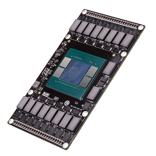 NVIDIA 3D |
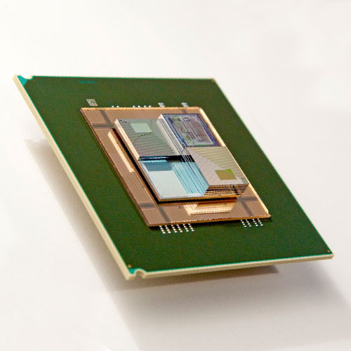 IBM Exascale |
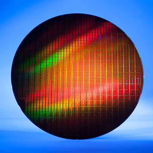 3D Wafer |
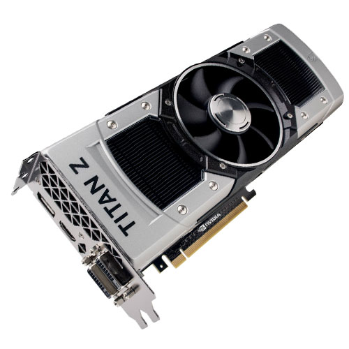 NVIDIA GPU |
NVIDIA 3D |
IBM Exascale |
3D Wafer |
NVIDIA GPU |
NVIDIA 3D |
IBM Exascale |
3D Wafer |
NVIDIA GPU |
NVIDIA 3D |
IBM Exascale |
3D Wafer |
NVIDIA GPU |
NVIDIA 3D |
IBM Exascale |
3D Wafer |
NVIDIA GPU |
| Invented in 1980 by Frederick (Rick) Dill, Daniel Ling & Richard Matick |
| Invented in 1980 by Frederick (Rick) Dill, Daniel Ling & Richard Matick |
| Invented in 1980 by Frederick (Rick) Dill, Daniel Ling & Richard Matick |
| Invented in 1980 by Frederick (Rick) Dill, Daniel Ling & Richard Matick |
| Invented in 1980 by Frederick (Rick) Dill, Daniel Ling & Richard Matick |
| AUDIO · COMMUNICATION · COMPUTER CONDUCTION · CONTROL · DISPLAY · ILLUMINATION MOTION · POWER · TEMPERATURE · IDENTITY |
| AUDIO · COMMUNICATION · COMPUTER CONDUCTION · CONTROL · DISPLAY · ILLUMINATION MOTION · POWER · TEMPERATURE · IDENTITY |
| AUDIO · COMMUNICATION · COMPUTER CONDUCTION · CONTROL · DISPLAY · ILLUMINATION MOTION · POWER · TEMPERATURE · IDENTITY |
| AUDIO · COMMUNICATION · COMPUTER CONDUCTION · CONTROL · DISPLAY · ILLUMINATION MOTION · POWER · TEMPERATURE · IDENTITY |
| AUDIO · COMMUNICATION · COMPUTER CONDUCTION · CONTROL · DISPLAY · ILLUMINATION MOTION · POWER · TEMPERATURE · IDENTITY |
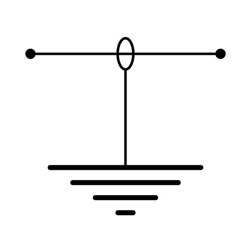 |
|
|
|
|
| Definition: A solid or stranded conductor typically of copper wire for electrical conductivity, or data optical fibre, or a combination of conductors insulated from one another for the transfer of information in telecommunications. |
| Definition: A solid or stranded conductor typically of copper wire for electrical conductivity, or data optical fibre, or a combination of conductors insulated from one another for the transfer of information in telecommunications. |
| Definition: A solid or stranded conductor typically of copper wire for electrical conductivity, or data optical fibre, or a combination of conductors insulated from one another for the transfer of information in telecommunications. |
| Definition: A solid or stranded conductor typically of copper wire for electrical conductivity, or data optical fibre, or a combination of conductors insulated from one another for the transfer of information in telecommunications. |
| Definition: A solid or stranded conductor typically of copper wire for electrical conductivity, or data optical fibre, or a combination of conductors insulated from one another for the transfer of information in telecommunications. |
 |
 |
 |
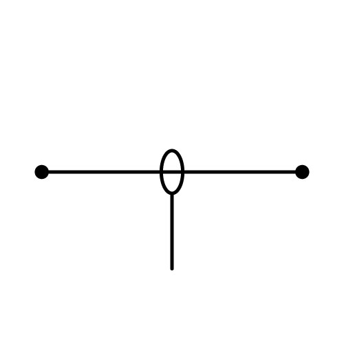 |
|
|
|
|
|
|
|
|
|
|
|
|
|
|
|
|
| History: The first power cable, known as a conductor, was made out of 270 metres of dampened hemp that was strung by silk to provide insulation. Electrical and communication cables are now made from single or multiple strands of copper (and at times aluminium) that are bonded, twisted, or braided together to form a single conductive assembly. Coated with silver or tin to protect from oxidation, along with resins and outer insulating jackets of plastics, rubbers and other fluoro-polymers. |
| Definition: The first power cable, known as a conductor, was made out of 270 metres of dampened hemp that was strung by silk to provide insulation. Electrical and communication cables are now made from single or multiple strands of copper (and at times aluminium) that are bonded, twisted, or braided together to form a single conductive assembly. Coated with silver or tin to protect from oxidation, along with resins and outer insulating jackets of plastics, rubbers and other fluoro-polymers. |
| Definition: The first power cable, known as a conductor, was made out of 270 metres of dampened hemp that was strung by silk to provide insulation. Electrical and communication cables are now made from single or multiple strands of copper (and at times aluminium) that are bonded, twisted, or braided together to form a single conductive assembly. Coated with silver or tin to protect from oxidation, along with resins and outer insulating jackets of plastics, rubbers and other fluoro-polymers. |
| Definition: The first power cable, known as a conductor, was made out of 270 metres of dampened hemp that was strung by silk to provide insulation. Electrical and communication cables are now made from single or multiple strands of copper (and at times aluminium) that are bonded, twisted, or braided together to form a single conductive assembly. Coated with silver or tin to protect from oxidation, along with resins and outer insulating jackets of plastics, rubbers and other fluoro-polymers. |
| Definition: The first power cable, known as a conductor, was made out of 270 metres of dampened hemp that was strung by silk to provide insulation. Electrical and communication cables are now made from single or multiple strands of copper (and at times aluminium) that are bonded, twisted, or braided together to form a single conductive assembly. Coated with silver or tin to protect from oxidation, along with resins and outer insulating jackets of plastics, rubbers and other fluoro-polymers. |
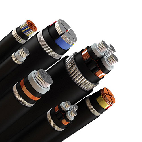 |
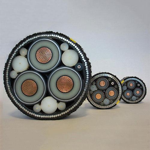 |
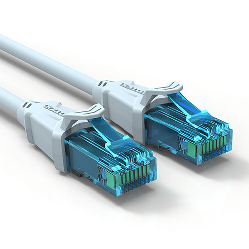 |
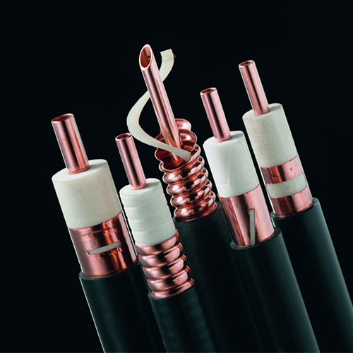 |
|
|
|
|
|
|
|
|
|
|
|
|
|
|
|
|
| Invented in 1730 by Stephen Gray. |
| Invented in 1730 by Stephen Gray. |
| Invented in 1730 by Stephen Gray. |
| Invented in 1730 by Stephen Gray. |
| Invented in 1730 by Stephen Gray. |
 |
|
|
|
|
| Definition: A circuit breaker is a device that will open circuit in the event of a fault condition. The traditional circuit breaker is a combination of a switch and automatic fuse and in the event of a short circuit or overload, the magnetic or thermal circuit breakers will open circuit within 0.05 second when the rated current of the device is exceeded. The safety switch (RCD) is a circuit breaker that will open circuit within 0.02 second of a detected current anomaly. This is fast enough to stop the flow of electricity from passing through a person to earth and faster than a cardiac cycle, significantly reducing the risk of death or injury. The ‘first trip time’ of most circuit breakers occur within 0.02 second, which will, after years of “no fault” activity extend to 300 milliseconds, highlighting the importance of regular annual trip testing. |
| Definition: A circuit breaker is a device that will open circuit in the event of a fault condition. The traditional circuit breaker is a combination of a switch and automatic fuse and in the event of a short circuit or overload, the magnetic or thermal circuit breakers will open circuit within 0.05 second when the rated current of the device is exceeded. The safety switch (RCD) is a circuit breaker that will open circuit within 0.02 second of a detected current anomaly. This is fast enough to stop the flow of electricity from passing through a person to earth and faster than a cardiac cycle, significantly reducing the risk of death or injury. The ‘first trip time’ of most circuit breakers occur within 0.02 second, which will, after years of “no fault” activity extend to 300 milliseconds, highlighting the importance of regular annual trip testing. |
| Definition: A circuit breaker is a device that will open circuit in the event of a fault condition. The traditional circuit breaker is a combination of a switch and automatic fuse and in the event of a short circuit or overload, the magnetic or thermal circuit breakers will open circuit within 0.05 second when the rated current of the device is exceeded. The safety switch (RCD) is a circuit breaker that will open circuit within 0.02 second of a detected current anomaly. This is fast enough to stop the flow of electricity from passing through a person to earth and faster than a cardiac cycle, significantly reducing the risk of death or injury. The ‘first trip time’ of most circuit breakers occur within 0.02 second, which will, after years of “no fault” activity extend to 300 milliseconds, highlighting the importance of regular annual trip testing. |
| Definition: A circuit breaker is a device that will open circuit in the event of a fault condition. The traditional circuit breaker is a combination of a switch and automatic fuse and in the event of a short circuit or overload, the magnetic or thermal circuit breakers will open circuit within 0.05 second when the rated current of the device is exceeded. The safety switch (RCD) is a circuit breaker that will open circuit within 0.02 second of a detected current anomaly. This is fast enough to stop the flow of electricity from passing through a person to earth and faster than a cardiac cycle, significantly reducing the risk of death or injury. The ‘first trip time’ of most circuit breakers occur within 0.02 second, which will, after years of “no fault” activity extend to 300 milliseconds, highlighting the importance of regular annual trip testing. |
| Definition: A circuit breaker is a device that will open circuit in the event of a fault condition. The traditional circuit breaker is a combination of a switch and automatic fuse and in the event of a short circuit or overload, the magnetic or thermal circuit breakers will open circuit within 0.05 second when the rated current of the device is exceeded. The safety switch (RCD) is a circuit breaker that will open circuit within 0.02 second of a detected current anomaly. This is fast enough to stop the flow of electricity from passing through a person to earth and faster than a cardiac cycle, significantly reducing the risk of death or injury. The ‘first trip time’ of most circuit breakers occur within 0.02 second, which will, after years of “no fault” activity extend to 300 milliseconds, highlighting the importance of regular annual trip testing. |
 |
 |
 |
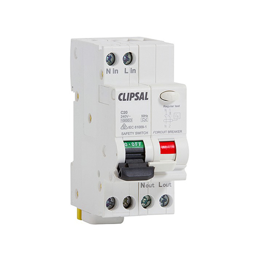 |
|
|
|
|
|
|
|
|
|
|
|
|
|
|
|
|
| Invented in 1927 by Hugo Stotz. |
| Invented in 1927 by Hugo Stotz. |
| Invented in 1927 by Hugo Stotz. |
| Invented in 1927 by Hugo Stotz. |
| Invented in 1927 by Hugo Stotz. |
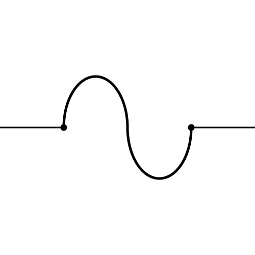 |
|
|
|
|
| Definition: Fuses are a protective device, designed to interrupt current flow (open) through a circuit when current exceeds a rated value. Thomas Edison later patented this existing component as part of his electrical distribution system. |
| Definition: Fuses are a protective device, designed to interrupt current flow (open) through a circuit when current exceeds a rated value. Thomas Edison later patented this existing component as part of his electrical distribution system. |
| Definition: Fuses are a protective device, designed to interrupt current flow (open) through a circuit when current exceeds a rated value. Thomas Edison later patented this existing component as part of his electrical distribution system. |
| Definition: Fuses are a protective device, designed to interrupt current flow (open) through a circuit when current exceeds a rated value. Thomas Edison later patented this existing component as part of his electrical distribution system. |
| Definition: Fuses are a protective device, designed to interrupt current flow (open) through a circuit when current exceeds a rated value. Thomas Edison later patented this existing component as part of his electrical distribution system. |
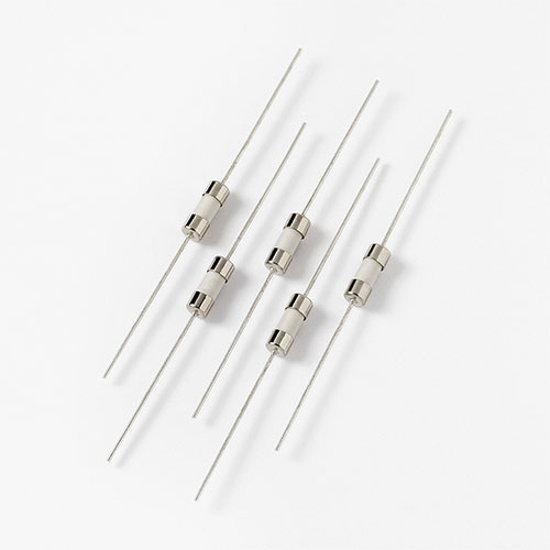 |
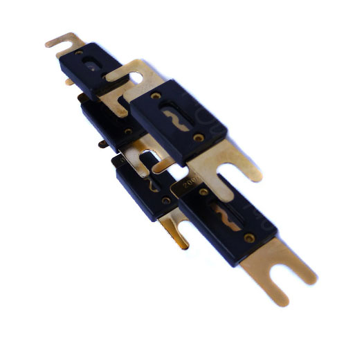 |
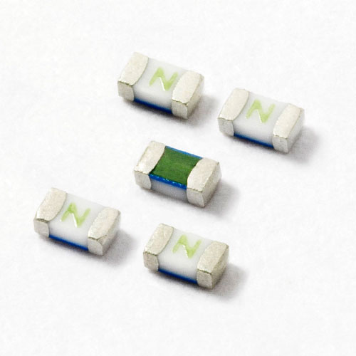 |
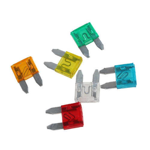 |
|
|
|
|
|
|
|
|
|
|
|
|
|
|
|
|
| Invented in 1847 by Louis-François-Clement Breguet. |
| Invented in 1847 by Louis-François-Clement Breguet. |
| Invented in 1847 by Louis-François-Clement Breguet. |
| Invented in 1847 by Louis-François-Clement Breguet. |
| Invented in 1847 by Louis-François-Clement Breguet. |
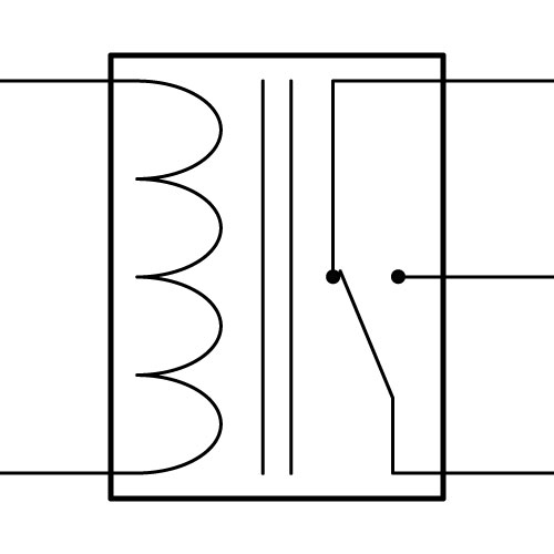 |
|
|
|
|
| Definition: This is an electromechanical device that uses electromagnetism to mechanically switch electrical circuits. Multiple output contacts are common and designed to be either normally open (NO) or normally closed (NC). The prime purpose of a relay is to provide circuit isolation and control power by energising a low current coil to switch a set of larger current contacts. Another use includes the switching of contacts to create logic (known as ladder logic), which can replicate the 7 logical gates of AND, NAND, OR, NOR, XOR, XNOR or NOT. |
| Definition: This is an electromechanical device that uses electromagnetism to mechanically switch electrical circuits. Multiple output contacts are common and designed to be either normally open (NO) or normally closed (NC). The prime purpose of a relay is to provide circuit isolation and control power by energising a low current coil to switch a set of larger current contacts. Another use includes the switching of contacts to create logic (known as ladder logic), which can replicate the 7 logical gates of AND, NAND, OR, NOR, XOR, XNOR or NOT. |
| Definition: This is an electromechanical device that uses electromagnetism to mechanically switch electrical circuits. Multiple output contacts are common and designed to be either normally open (NO) or normally closed (NC). The prime purpose of a relay is to provide circuit isolation and control power by energising a low current coil to switch a set of larger current contacts. Another use includes the switching of contacts to create logic (known as ladder logic), which can replicate the 7 logical gates of AND, NAND, OR, NOR, XOR, XNOR or NOT. |
| Definition: This is an electromechanical device that uses electromagnetism to mechanically switch electrical circuits. Multiple output contacts are common and designed to be either normally open (NO) or normally closed (NC). The prime purpose of a relay is to provide circuit isolation and control power by energising a low current coil to switch a set of larger current contacts. Another use includes the switching of contacts to create logic (known as ladder logic), which can replicate the 7 logical gates of AND, NAND, OR, NOR, XOR, XNOR or NOT. |
| Definition: This is an electromechanical device that uses electromagnetism to mechanically switch electrical circuits. Multiple output contacts are common and designed to be either normally open (NO) or normally closed (NC). The prime purpose of a relay is to provide circuit isolation and control power by energising a low current coil to switch a set of larger current contacts. Another use includes the switching of contacts to create logic (known as ladder logic), which can replicate the 7 logical gates of AND, NAND, OR, NOR, XOR, XNOR or NOT. |
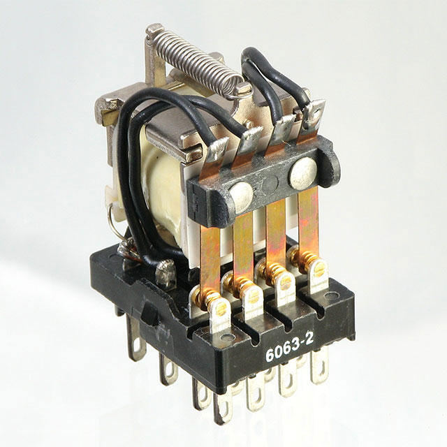 |
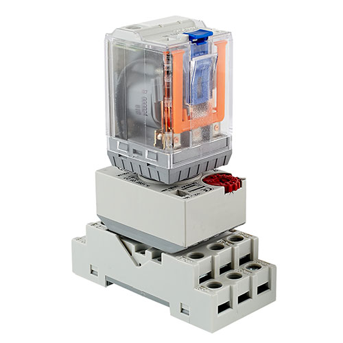 |
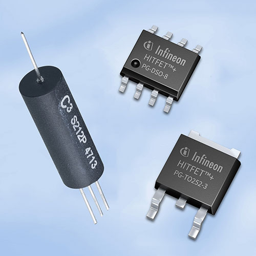 |
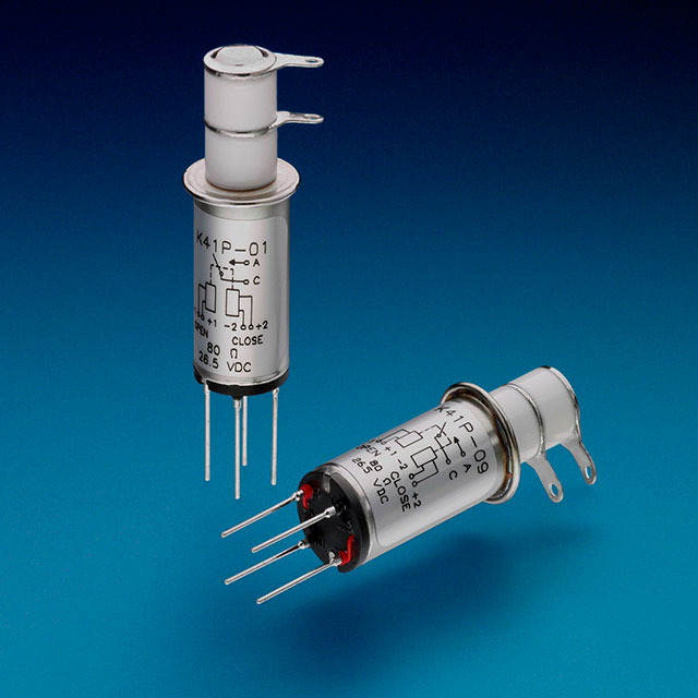 |
|
|
|
|
|
|
|
|
|
|
|
|
|
|
|
|
| Invented in 1840 by Samuel Morse. |
| Invented in 1840 by Samuel Morse. |
| Invented in 1840 by Samuel Morse. |
| Invented in 1840 by Samuel Morse. |
| Invented in 1840 by Samuel Morse. |
| AUDIO · COMMUNICATION · COMPUTER CONDUCTION · CONTROL · DISPLAY · ILLUMINATION MOTION · POWER · TEMPERATURE · IDENTITY |
| AUDIO · COMMUNICATION · COMPUTER CONDUCTION · CONTROL · DISPLAY · ILLUMINATION MOTION · POWER · TEMPERATURE · IDENTITY |
| AUDIO · COMMUNICATION · COMPUTER CONDUCTION · CONTROL · DISPLAY · ILLUMINATION MOTION · POWER · TEMPERATURE · IDENTITY |
| AUDIO · COMMUNICATION · COMPUTER CONDUCTION · CONTROL · DISPLAY · ILLUMINATION MOTION · POWER · TEMPERATURE · IDENTITY |
| AUDIO · COMMUNICATION · COMPUTER CONDUCTION · CONTROL · DISPLAY · ILLUMINATION MOTION · POWER · TEMPERATURE · IDENTITY |
 |
|
|
|
|
| Definition: This device reduces the power of a signal without distorting its waveform and are made from simple voltage divider networks of resistors. They are the opposite of an amplifier providing gain, an attenuator provides loss. Used in circuits to lower voltage, dissipate power, and to improve impedance matching. |
| Definition: This device reduces the power of a signal without distorting its waveform and are made from simple voltage divider networks of resistors. They are the opposite of an amplifier providing gain, an attenuator provides loss. Used in circuits to lower voltage, dissipate power, and to improve impedance matching. |
| Definition: This device reduces the power of a signal without distorting its waveform and are made from simple voltage divider networks of resistors. They are the opposite of an amplifier providing gain, an attenuator provides loss. Used in circuits to lower voltage, dissipate power, and to improve impedance matching. |
| Definition: This device reduces the power of a signal without distorting its waveform and are made from simple voltage divider networks of resistors. They are the opposite of an amplifier providing gain, an attenuator provides loss. Used in circuits to lower voltage, dissipate power, and to improve impedance matching. |
| Definition: This device reduces the power of a signal without distorting its waveform and are made from simple voltage divider networks of resistors. They are the opposite of an amplifier providing gain, an attenuator provides loss. Used in circuits to lower voltage, dissipate power, and to improve impedance matching. |
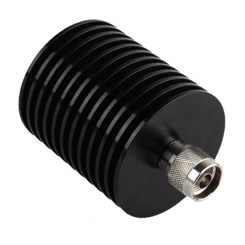 |
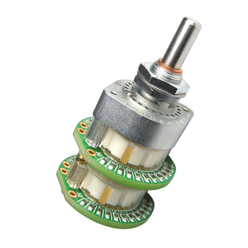 |
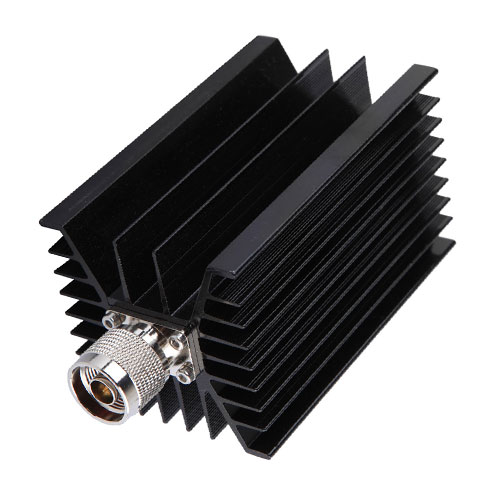 |
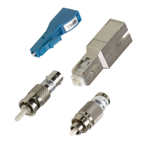 |
|
|
|
|
|
|
|
|
|
|
|
|
|
|
|
|
| Invented in 1925 by Olindo Oreste Ceccarini. |
| Invented in 1925 by Olindo Oreste Ceccarini. |
| Invented in 1925 by Olindo Oreste Ceccarini. |
| Invented in 1925 by Olindo Oreste Ceccarini. |
| Invented in 1925 by Olindo Oreste Ceccarini. |
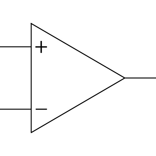 |
|
|
|
|
| Definition: This device compares the values of two analogue inputs and generates a digital square wave output with high and low values. Used to convert a sine wave to a square wave or to control a set point value to control temperature by calibrating to the voltage provided by a thermocouple to a known temperature. |
| Definition: This device compares the values of two analogue inputs and generates a digital square wave output with high and low values. Used to convert a sine wave to a square wave or to control a set point value to control temperature by calibrating to the voltage provided by a thermocouple to a known temperature. |
| Definition: This device compares the values of two analogue inputs and generates a digital square wave output with high and low values. Used to convert a sine wave to a square wave or to control a set point value to control temperature by calibrating to the voltage provided by a thermocouple to a known temperature. |
| Definition: This device compares the values of two analogue inputs and generates a digital square wave output with high and low values. Used to convert a sine wave to a square wave or to control a set point value to control temperature by calibrating to the voltage provided by a thermocouple to a known temperature. |
| Definition: This device compares the values of two analogue inputs and generates a digital square wave output with high and low values. Used to convert a sine wave to a square wave or to control a set point value to control temperature by calibrating to the voltage provided by a thermocouple to a known temperature. |
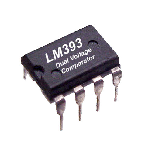 |
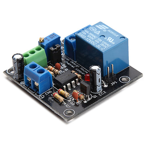 |
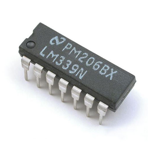 |
 |
|
|
|
|
|
|
|
|
|
|
|
|
|
|
|
|
| Invented in 1953 by Robert Royce Johnson. |
| Invented in 1953 by Robert Royce Johnson. |
| Invented in 1953 by Robert Royce Johnson. |
| Invented in 1953 by Robert Royce Johnson. |
| Invented in 1953 by Robert Royce Johnson. |
 |
|
|
|
|
| Definition: Crystal oscillators supply a source of electrical oscillations of very constant frequency determined by the physical characteristics of a quartz crystal. They utilise the mechanical resonance of a vibrating crystal of piezoelectric material to create an electrical signal with a precise frequency. They are used within clocks and to provide a stable clock signal for digital integrated circuits and to stabilise frequencies in radio circuits. |
| Definition: Crystal oscillators supply a source of electrical oscillations of very constant frequency determined by the physical characteristics of a quartz crystal. They utilise the mechanical resonance of a vibrating crystal of piezoelectric material to create an electrical signal with a precise frequency. They are used within clocks and to provide a stable clock signal for digital integrated circuits and to stabilise frequencies in radio circuits. |
| Definition: Crystal oscillators supply a source of electrical oscillations of very constant frequency determined by the physical characteristics of a quartz crystal. They utilise the mechanical resonance of a vibrating crystal of piezoelectric material to create an electrical signal with a precise frequency. They are used within clocks and to provide a stable clock signal for digital integrated circuits and to stabilise frequencies in radio circuits. |
| Definition: Crystal oscillators supply a source of electrical oscillations of very constant frequency determined by the physical characteristics of a quartz crystal. They utilise the mechanical resonance of a vibrating crystal of piezoelectric material to create an electrical signal with a precise frequency. They are used within clocks and to provide a stable clock signal for digital integrated circuits and to stabilise frequencies in radio circuits. |
| Definition: Crystal oscillators supply a source of electrical oscillations of very constant frequency determined by the physical characteristics of a quartz crystal. They utilise the mechanical resonance of a vibrating crystal of piezoelectric material to create an electrical signal with a precise frequency. They are used within clocks and to provide a stable clock signal for digital integrated circuits and to stabilise frequencies in radio circuits. |
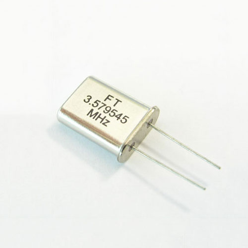 |
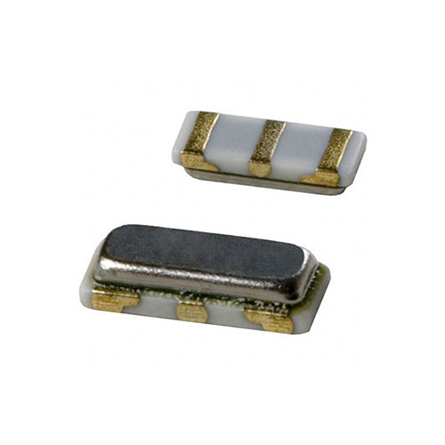 |
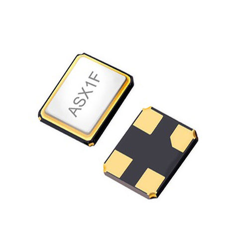 |
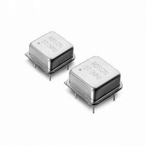 |
|
|
|
|
|
|
|
|
|
|
|
|
|
|
|
|
| Invented in 1918 by Walter Guyton Cady. |
| Invented in 1918 by Walter Guyton Cady. |
| Invented in 1918 by Walter Guyton Cady. |
| Invented in 1918 by Walter Guyton Cady. |
| Invented in 1918 by Walter Guyton Cady. |
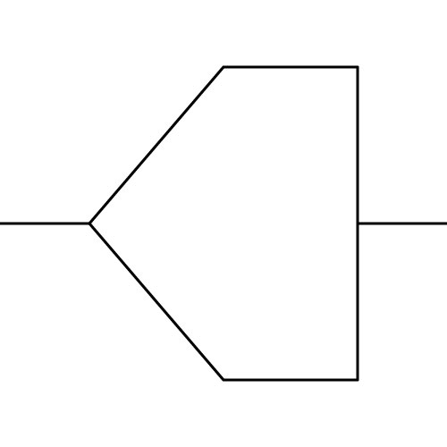 ADC |
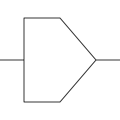 DAC |
|
|
|
|
|
|
|
|
| Definition: Analogue-to-Digital Converter, ADC, is a circuit or device that is used to replicate an analogue signal to a digital representation of that waveform. A Digital-to-Analogue Converter, DAC, is a circuit or device that is used to convert a binary signal to an equivalent analogue waveform. |
| Definition: Analogue-to-Digital Converter, ADC, is a circuit or device that is used to replicate an analogue signal to a digital representation of that waveform. A Digital-to-Analogue Converter, DAC, is a circuit or device that is used to convert a binary signal to an equivalent analogue waveform. |
| Definition: Analogue-to-Digital Converter, ADC, is a circuit or device that is used to replicate an analogue signal to a digital representation of that waveform. A Digital-to-Analogue Converter, DAC, is a circuit or device that is used to convert a binary signal to an equivalent analogue waveform. |
| Definition: Analogue-to-Digital Converter, ADC, is a circuit or device that is used to replicate an analogue signal to a digital representation of that waveform. A Digital-to-Analogue Converter, DAC, is a circuit or device that is used to convert a binary signal to an equivalent analogue waveform. |
| Definition: Analogue-to-Digital Converter, ADC, is a circuit or device that is used to replicate an analogue signal to a digital representation of that waveform. A Digital-to-Analogue Converter, DAC, is a circuit or device that is used to convert a binary signal to an equivalent analogue waveform. |
| Invented in 1953 by Bernard Marshall Gordon. |
| Invented in 1953 by Bernard Marshall Gordon. |
| Invented in 1953 by Bernard Marshall Gordon. |
| Invented in 1953 by Bernard Marshall Gordon. |
| Invented in 1953 by Bernard Marshall Gordon. |
| AUDIO · COMMUNICATION · COMPUTER CONDUCTION · CONTROL · DISPLAY · ILLUMINATION MOTION · POWER · TEMPERATURE · IDENTITY |
| AUDIO · COMMUNICATION · COMPUTER CONDUCTION · CONTROL · DISPLAY · ILLUMINATION MOTION · POWER · TEMPERATURE · IDENTITY |
| AUDIO · COMMUNICATION · COMPUTER CONDUCTION · CONTROL · DISPLAY · ILLUMINATION MOTION · POWER · TEMPERATURE · IDENTITY |
| AUDIO · COMMUNICATION · COMPUTER CONDUCTION · CONTROL · DISPLAY · ILLUMINATION MOTION · POWER · TEMPERATURE · IDENTITY |
| AUDIO · COMMUNICATION · COMPUTER CONDUCTION · CONTROL · DISPLAY · ILLUMINATION MOTION · POWER · TEMPERATURE · IDENTITY |
| Cathode Ray Tube, CRT |
| Cathode Ray Tube, CRT |
| Cathode Ray Tube, CRT |
| Cathode Ray Tube, CRT |
| Cathode Ray Tube, CRT |
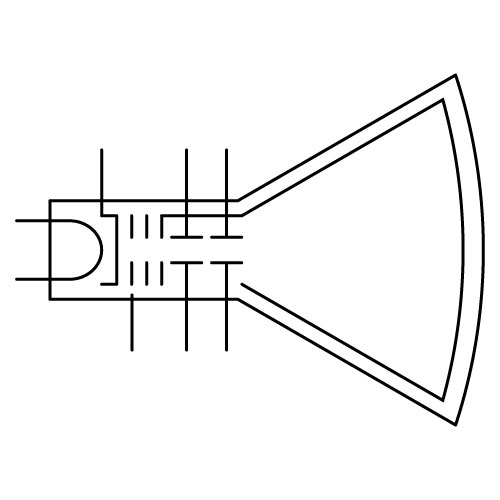 |
|
|
|
|
| Definition: The Cathode Ray Tube, CRT, also known as the “Braun tube”, is a vacuum tube containing electron guns to accelerate and deflect the electron beam(s) onto the phosphorescent screen to view images. The images may represent electrical waveforms as in an oscilloscope, pictures or radar targets. The CRT uses an evacuated glass envelope with the face typically made of thick lead glass for shatter-resistance and to block most X-ray emissions. |
| Definition: The Cathode Ray Tube, CRT, also known as the “Braun tube”, is a vacuum tube containing electron guns to accelerate and deflect the electron beam(s) onto the phosphorescent screen to view images. The images may represent electrical waveforms as in an oscilloscope, pictures or radar targets. The CRT uses an evacuated glass envelope with the face typically made of thick lead glass for shatter-resistance and to block most X-ray emissions. |
| Definition: The Cathode Ray Tube, CRT, also known as the “Braun tube”, is a vacuum tube containing electron guns to accelerate and deflect the electron beam(s) onto the phosphorescent screen to view images. The images may represent electrical waveforms as in an oscilloscope, pictures or radar targets. The CRT uses an evacuated glass envelope with the face typically made of thick lead glass for shatter-resistance and to block most X-ray emissions. |
| Definition: The Cathode Ray Tube, CRT, also known as the “Braun tube”, is a vacuum tube containing electron guns to accelerate and deflect the electron beam(s) onto the phosphorescent screen to view images. The images may represent electrical waveforms as in an oscilloscope, pictures or radar targets. The CRT uses an evacuated glass envelope with the face typically made of thick lead glass for shatter-resistance and to block most X-ray emissions. |
| Definition: The Cathode Ray Tube, CRT, also known as the “Braun tube”, is a vacuum tube containing electron guns to accelerate and deflect the electron beam(s) onto the phosphorescent screen to view images. The images may represent electrical waveforms as in an oscilloscope, pictures or radar targets. The CRT uses an evacuated glass envelope with the face typically made of thick lead glass for shatter-resistance and to block most X-ray emissions. |
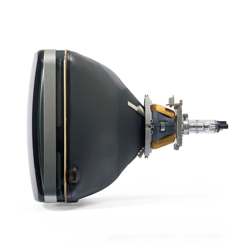 |
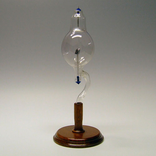 |
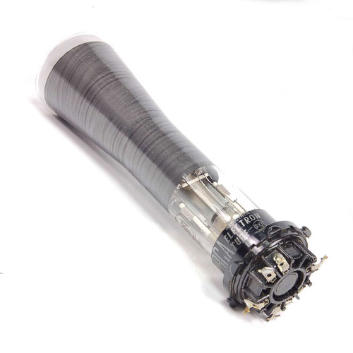 |
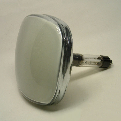 |
|
|
|
|
|
|
|
|
|
|
|
|
|
|
|
|
| Invented in 1897 by Karl Ferdinand Braun. |
| Invented in 1897 by Karl Ferdinand Braun. |
| Invented in 1897 by Karl Ferdinand Braun. |
| Invented in 1897 by Karl Ferdinand Braun. |
| Invented in 1897 by Karl Ferdinand Braun. |
 |
|
|
|
|
| Definition: Electroluminescent Displays, ELDs are formed by layering electroluminescent materials between two layers of conductors, and with a supplied current, radiation is emitted in the form of visible light. Electroluminescence is when excited electrons release their energy as photons within a semiconductor material, by doping the material to form a p-n junction or as a result of an impact of high-energy electrons accelerated by a strong electric field. |
| Definition: Electroluminescent Displays, ELDs are formed by layering electroluminescent materials between two layers of conductors, and with a supplied current, radiation is emitted in the form of visible light. Electroluminescence is when excited electrons release their energy as photons within a semiconductor material, by doping the material to form a p-n junction or as a result of an impact of high-energy electrons accelerated by a strong electric field. |
| Definition: Electroluminescent Displays, ELDs are formed by layering electroluminescent materials between two layers of conductors, and with a supplied current, radiation is emitted in the form of visible light. Electroluminescence is when excited electrons release their energy as photons within a semiconductor material, by doping the material to form a p-n junction or as a result of an impact of high-energy electrons accelerated by a strong electric field. |
| Definition: Electroluminescent Displays, ELDs are formed by layering electroluminescent materials between two layers of conductors, and with a supplied current, radiation is emitted in the form of visible light. Electroluminescence is when excited electrons release their energy as photons within a semiconductor material, by doping the material to form a p-n junction or as a result of an impact of high-energy electrons accelerated by a strong electric field. |
| Definition: Electroluminescent Displays, ELDs are formed by layering electroluminescent materials between two layers of conductors, and with a supplied current, radiation is emitted in the form of visible light. Electroluminescence is when excited electrons release their energy as photons within a semiconductor material, by doping the material to form a p-n junction or as a result of an impact of high-energy electrons accelerated by a strong electric field. |
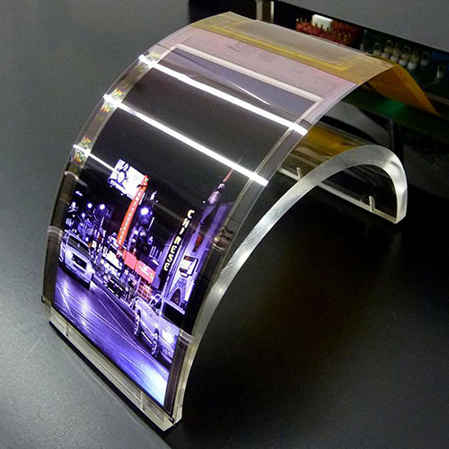 |
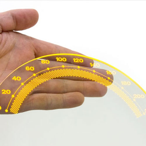 |
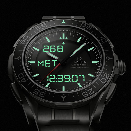 |
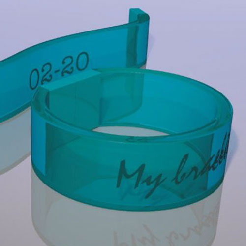 |
|
|
|
|
|
|
|
|
|
|
|
|
|
|
|
|
| Invented in 1972 by Bródy Tamás Péter. |
| Invented in 1972 by Bródy Tamás Péter. |
| Invented in 1972 by Bródy Tamás Péter. |
| Invented in 1972 by Bródy Tamás Péter. |
| Invented in 1972 by Bródy Tamás Péter. |
 |
|
|
|
|
| Definition: The Light Emitting Diode Display, utilises an array of RGB (Red, Green and Blue) light emitting diodes as pixels for a video display. Used primarily as signs and billboards, the LED brightness allows for them to be used outdoors in direct sunlight. |
| Definition: The Light Emitting Diode Display, utilises an array of RGB (Red, Green and Blue) light emitting diodes as pixels for a video display. Used primarily as signs and billboards, the LED brightness allows for them to be used outdoors in direct sunlight. |
| Definition: The Light Emitting Diode Display, utilises an array of RGB (Red, Green and Blue) light emitting diodes as pixels for a video display. Used primarily as signs and billboards, the LED brightness allows for them to be used outdoors in direct sunlight. |
| Definition: The Light Emitting Diode Display, utilises an array of RGB (Red, Green and Blue) light emitting diodes as pixels for a video display. Used primarily as signs and billboards, the LED brightness allows for them to be used outdoors in direct sunlight. |
| Definition: The Light Emitting Diode Display, utilises an array of RGB (Red, Green and Blue) light emitting diodes as pixels for a video display. Used primarily as signs and billboards, the LED brightness allows for them to be used outdoors in direct sunlight. |
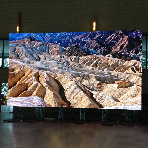 |
 |
 |
 |
|
|
|
|
|
|
|
|
|
|
|
|
|
|
|
|
| Invented in 1977 by James Mitchell. |
| Invented in 1977 by James Mitchell. |
| Invented in 1977 by James Mitchell. |
| Invented in 1977 by James Mitchell. |
| Invented in 1977 by James Mitchell. |
 |
|
|
|
|
| Definition: The Liquid Crystal Display, LCD is the product of polarising filter film, glass substrate, electrodes, twisted nematic liquid crystal and a LED backlight. Used in computer monitors, televisions, instrumentation panels and sign displays, they have replaced cathode ray tube (CRT) displays and as they do not use phosphors, they do not suffer from image burn-in. |
| Definition: The Liquid Crystal Display, LCD is the product of polarising filter film, glass substrate, electrodes, twisted nematic liquid crystal and a LED backlight. Used in computer monitors, televisions, instrumentation panels and sign displays, they have replaced cathode ray tube (CRT) displays and as they do not use phosphors, they do not suffer from image burn-in. |
| Definition: The Liquid Crystal Display, LCD is the product of polarising filter film, glass substrate, electrodes, twisted nematic liquid crystal and a LED backlight. Used in computer monitors, televisions, instrumentation panels and sign displays, they have replaced cathode ray tube (CRT) displays and as they do not use phosphors, they do not suffer from image burn-in. |
| Definition: The Liquid Crystal Display, LCD is the product of polarising filter film, glass substrate, electrodes, twisted nematic liquid crystal and a LED backlight. Used in computer monitors, televisions, instrumentation panels and sign displays, they have replaced cathode ray tube (CRT) displays and as they do not use phosphors, they do not suffer from image burn-in. |
| Definition: The Liquid Crystal Display, LCD is the product of polarising filter film, glass substrate, electrodes, twisted nematic liquid crystal and a LED backlight. Used in computer monitors, televisions, instrumentation panels and sign displays, they have replaced cathode ray tube (CRT) displays and as they do not use phosphors, they do not suffer from image burn-in. |
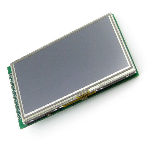 |
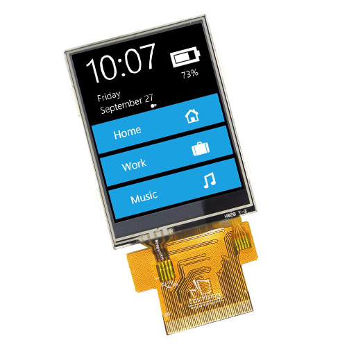 |
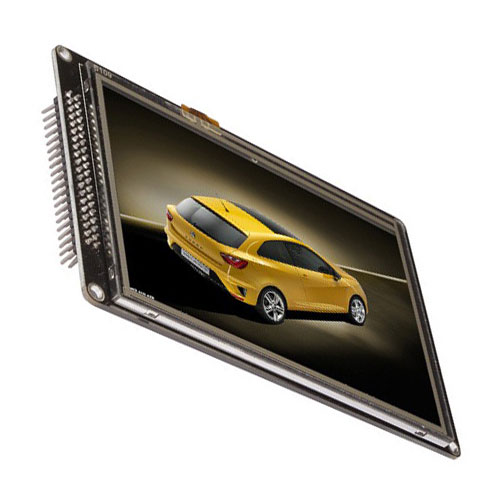 |
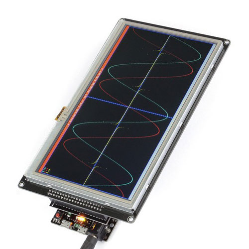 |
|
|
|
|
|
|
|
|
|
|
|
|
|
|
|
|
| Invented in 1965 by George Harry Heilmeier. |
| Invented in 1965 by George Harry Heilmeier. |
| Invented in 1965 by George Harry Heilmeier. |
| Invented in 1965 by George Harry Heilmeier. |
| Invented in 1965 by George Harry Heilmeier. |
 |
|
|
|
|
| Definition: An organic light-emitting diode, OLED is a light-emitting diode (LED) in which emissions from an electroluminescent layer, a film of organic compound that emits light in response to an electric current and arranged in a grid array. |
| Definition: An organic light-emitting diode, OLED is a light-emitting diode (LED) in which emissions from an electroluminescent layer, a film of organic compound that emits light in response to an electric current and arranged in a grid array. |
| Definition: An organic light-emitting diode, OLED is a light-emitting diode (LED) in which emissions from an electroluminescent layer, a film of organic compound that emits light in response to an electric current and arranged in a grid array. |
| Definition: An organic light-emitting diode, OLED is a light-emitting diode (LED) in which emissions from an electroluminescent layer, a film of organic compound that emits light in response to an electric current and arranged in a grid array. |
| Definition: An organic light-emitting diode, OLED is a light-emitting diode (LED) in which emissions from an electroluminescent layer, a film of organic compound that emits light in response to an electric current and arranged in a grid array. |
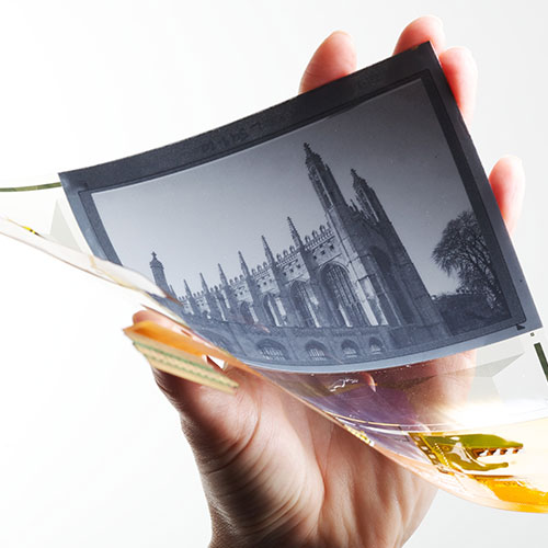 |
 |
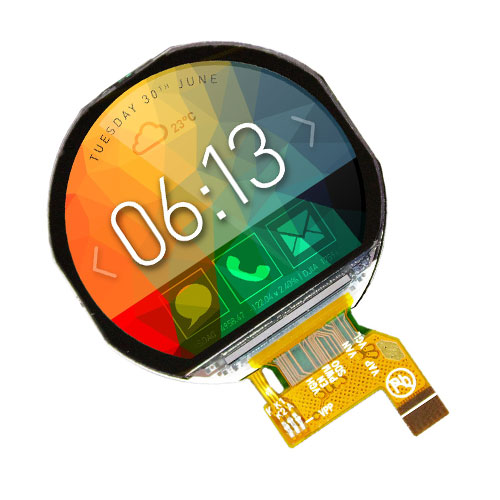 |
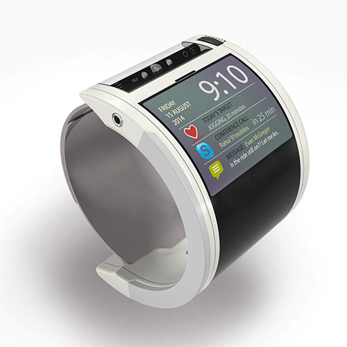 |
|
|
|
|
|
|
|
|
|
|
|
|
|
|
|
|
| Invented in 1987 by Ching W Tang & Steven Van Slyke. |
| Invented in 1987 by Ching W Tang & Steven Van Slyke. |
| Invented in 1987 by Ching W Tang & Steven Van Slyke. |
| Invented in 1987 by Ching W Tang & Steven Van Slyke. |
| Invented in 1987 by Ching W Tang & Steven Van Slyke. |
 |
|
|
|
|
| Definition: Plasma displays have a brightness that exceeds 1,000 lux. They are called “plasma” displays as they use small cells that contain electrically charged ionised gases, which are plasmas. |
| Definition: Plasma displays have a brightness that exceeds 1,000 lux. They are called “plasma” displays as they use small cells that contain electrically charged ionised gases, which are plasmas. |
| Definition: Plasma displays have a brightness that exceeds 1,000 lux. They are called “plasma” displays as they use small cells that contain electrically charged ionised gases, which are plasmas. |
| Definition: Plasma displays have a brightness that exceeds 1,000 lux. They are called “plasma” displays as they use small cells that contain electrically charged ionised gases, which are plasmas. |
| Definition: Plasma displays have a brightness that exceeds 1,000 lux. They are called “plasma” displays as they use small cells that contain electrically charged ionised gases, which are plasmas. |
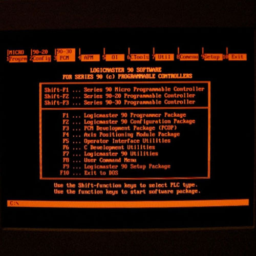 |
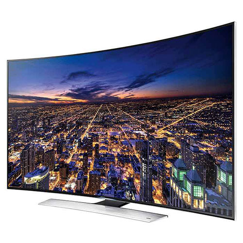 |
 |
 |
|
|
|
|
|
|
|
|
|
|
|
|
|
|
|
|
| Invented in 1987 by Gene Slottow, Donald Bitzer. & Robert Wilson. |
| Invented in 1987 by Gene Slottow, Donald Bitzer. & Robert Wilson. |
| Invented in 1987 by Gene Slottow, Donald Bitzer. & Robert Wilson. |
| Invented in 1987 by Gene Slottow, Donald Bitzer. & Robert Wilson. |
| Invented in 1987 by Gene Slottow, Donald Bitzer. & Robert Wilson. |
 |
|
|
|
|
| Definition: Similar to a cathode-ray tube, CRT, Vacuum Fluorescent Display works by heating a metal known as a cathode, which in turn fires electrons to a glass screen, coated with chemicals known as phosphors that glow when hit by electrons. By controlling the electron beam using magnets and a metal grid, a pattern of glowing dots on the screen can be changed create a different image. |
| Definition: Similar to a cathode-ray tube, CRT, Vacuum Fluorescent Display works by heating a metal known as a cathode, which in turn fires electrons to a glass screen, coated with chemicals known as phosphors that glow when hit by electrons. By controlling the electron beam using magnets and a metal grid, a pattern of glowing dots on the screen can be changed create a different image. |
| Definition: Similar to a cathode-ray tube, CRT, Vacuum Fluorescent Display works by heating a metal known as a cathode, which in turn fires electrons to a glass screen, coated with chemicals known as phosphors that glow when hit by electrons. By controlling the electron beam using magnets and a metal grid, a pattern of glowing dots on the screen can be changed create a different image. |
| Definition: Similar to a cathode-ray tube, CRT, Vacuum Fluorescent Display works by heating a metal known as a cathode, which in turn fires electrons to a glass screen, coated with chemicals known as phosphors that glow when hit by electrons. By controlling the electron beam using magnets and a metal grid, a pattern of glowing dots on the screen can be changed create a different image. |
| Definition: Plasma displays have a brightness that exceeds 1,000 lux. They are called “plasma” displays as they use small cells that contain electrically charged ionised gases, which are plasmas. |
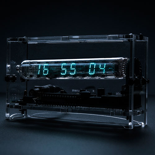 |
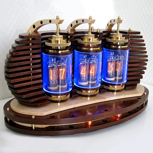 |
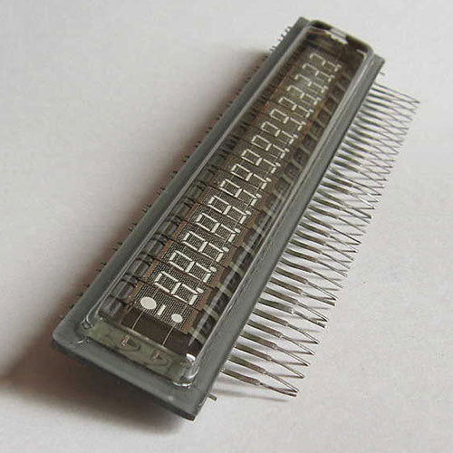 |
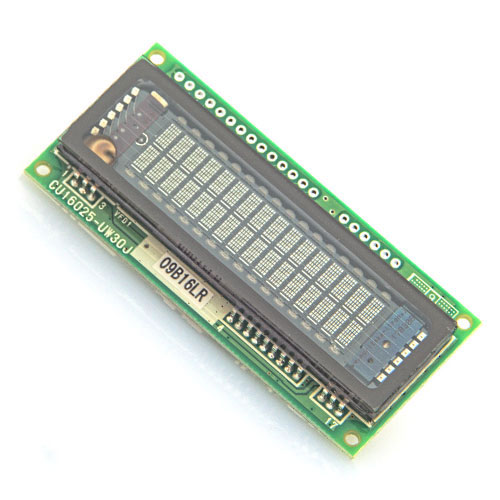 |
|
|
|
|
|
|
|
|
|
|
|
|
|
|
|
|
| Invented in 1959 by John Zappaoosta. |
| Invented in 1959 by John Zappaoosta. |
| Invented in 1959 by John Zappaoosta. |
| Invented in 1959 by John Zappaoosta. |
| Invented in 1959 by John Zappaoosta. |
| AUDIO · COMMUNICATION · COMPUTER CONDUCTION · CONTROL · DISPLAY · ILLUMINATION MOTION · POWER · TEMPERATURE · IDENTITY |
| AUDIO · COMMUNICATION · COMPUTER CONDUCTION · CONTROL · DISPLAY · ILLUMINATION MOTION · POWER · TEMPERATURE · IDENTITY |
| AUDIO · COMMUNICATION · COMPUTER CONDUCTION · CONTROL · DISPLAY · ILLUMINATION MOTION · POWER · TEMPERATURE · IDENTITY |
| AUDIO · COMMUNICATION · COMPUTER CONDUCTION · CONTROL · DISPLAY · ILLUMINATION MOTION · POWER · TEMPERATURE · IDENTITY |
| AUDIO · COMMUNICATION · COMPUTER CONDUCTION · CONTROL · DISPLAY · ILLUMINATION MOTION · POWER · TEMPERATURE · IDENTITY |
 |
|
|
|
|
| Definition: Used to provide starting current for certain types of lamps. When loads have a terminal voltage decline when current through the load increases, it will draw an increasing amount of current until it was destroyed or caused the power supply to fail. To remedy this, a ballast is to provide a positive resistance or reactance to limit this current. |
| Definition: Used to provide starting current for certain types of lamps. When loads have a terminal voltage decline when current through the load increases, it will draw an increasing amount of current until it was destroyed or caused the power supply to fail. To remedy this, a ballast is to provide a positive resistance or reactance to limit this current. |
| Definition: Used to provide starting current for certain types of lamps. When loads have a terminal voltage decline when current through the load increases, it will draw an increasing amount of current until it was destroyed or caused the power supply to fail. To remedy this, a ballast is to provide a positive resistance or reactance to limit this current. |
| Definition: Used to provide starting current for certain types of lamps. When loads have a terminal voltage decline when current through the load increases, it will draw an increasing amount of current until it was destroyed or caused the power supply to fail. To remedy this, a ballast is to provide a positive resistance or reactance to limit this current. |
| Definition: Used to provide starting current for certain types of lamps. When loads have a terminal voltage decline when current through the load increases, it will draw an increasing amount of current until it was destroyed or caused the power supply to fail. To remedy this, a ballast is to provide a positive resistance or reactance to limit this current. |
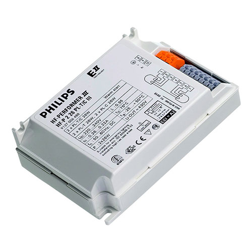 |
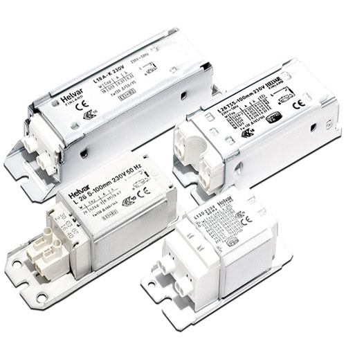 |
 |
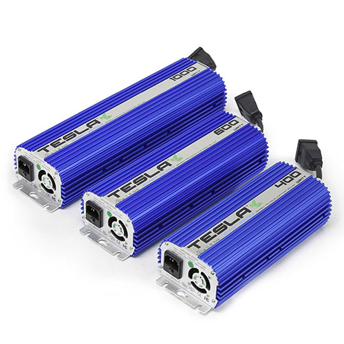 |
|
|
|
|
|
|
|
|
|
|
|
|
|
|
|
|
| Invented in 1936 by George Elmer Inman. |
| Invented in 1936 by George Elmer Inman. |
| Invented in 1936 by George Elmer Inman. |
| Invented in 1936 by George Elmer Inman. |
| Invented in 1936 by George Elmer Inman. |
 |
|
|
|
|
| Definition: Electroluminescence light is produced when excited electrons release their energy as photons within a semiconductor material, by doping the material to form a p-n junction or as a result of an impact of high-energy electrons accelerated by a strong electric field. |
| Definition: Electroluminescence light is produced when excited electrons release their energy as photons within a semiconductor material, by doping the material to form a p-n junction or as a result of an impact of high-energy electrons accelerated by a strong electric field. |
| Definition: Electroluminescence light is produced when excited electrons release their energy as photons within a semiconductor material, by doping the material to form a p-n junction or as a result of an impact of high-energy electrons accelerated by a strong electric field. |
| Definition: Electroluminescence light is produced when excited electrons release their energy as photons within a semiconductor material, by doping the material to form a p-n junction or as a result of an impact of high-energy electrons accelerated by a strong electric field. |
| Definition: Electroluminescence light is produced when excited electrons release their energy as photons within a semiconductor material, by doping the material to form a p-n junction or as a result of an impact of high-energy electrons accelerated by a strong electric field. |
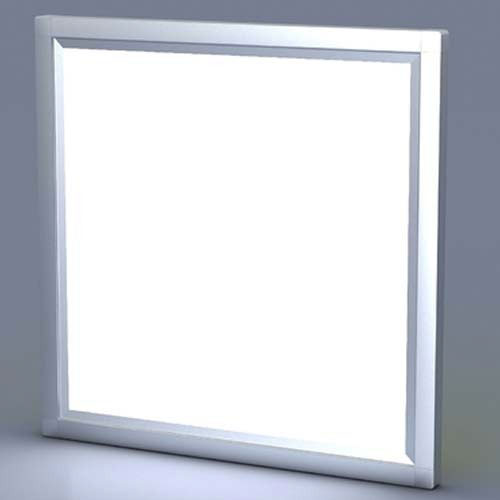 |
 |
 |
 |
|
|
|
|
|
|
|
|
|
|
|
|
|
|
|
|
| Invented in 1907 by Henry Joseph Round. |
| Invented in 1907 by Henry Joseph Round. |
| Invented in 1907 by Henry Joseph Round. |
| Invented in 1907 by Henry Joseph Round. |
| Invented in 1907 by Henry Joseph Round. |
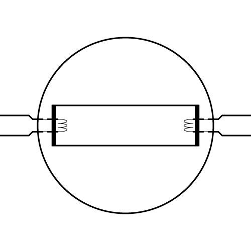 |
|
|
|
|
| Definition: Incandescent lighting is a result of heating a filament by electricity which exhibits resistance that result in high temperatures causing the filament to glow and emit light. Arc, vapour and fluorescent lamps work by creating light as a consequence of chemical reactions that occur when electricity is applied to gases within a glass vacuum chamber. There are a number of inventors that have attempted to create the incandescent and fluorescent light and have achieved by way of making a light source yet failed by not consistently producing the right temperature (colour) of light or the right luminous intensity. The following dates recognise and showcase the co-inventors of our modern fluorescent tube: 1856, Heinrich Geissler extensively studied the arc tube and created his Geissler tube which became the foundation for all arc discharge and HID lamps. 1859, Alexandre Edmond Becquerel was the first to use phosphors to coat the inside of a glass discharge tube. 1891, Nikola Tesla created an induction lamp with green phosphors without electrodes and high frequency ballast, the predecessor to the modern fluorescent ballasts. 1895, Daniel McFarlan Moore achieved success creating the Moore Tube, the first predecessor to the fluorescent light. Resembling the tube of today, yet longer and used Carbon Dioxide and Nitrogen, illuminating pink and white light. 1896, Thomas Edison made a light with a calcium tungstate phosphor coating, was excited by x-rays and only lasted a very short time. Development stopped after Clarence Dally who helped Edison build his lamp, died after exposure to radiation. 1901, Peter Cooper Hewitt developed the first mercury vapour lamp for commercial use and his work pertaining to electrodes and ballasts, formed the basis from which modern fluorescent tubes operate today. The use of an electric arc through mercury vapour is the basis for the modern fluorescent lamp, yet it would be 20 more years before mercury vapour was used within the fluorescent lamp. 1911, William D Coolidge developed a ductile tungsten wire, one of the highest melting points of any metal and perfect for all arc discharge lamps, fluorescent, vacuum and x-ray tubes. 1915, Georges Claude invented the modern neon lamp, a simple form of fluorescent lamp, with neon and argon gas in a tube with two electrodes. The original neon lamps did not use a phosphor and is considered a cold cathode fluorescent lamp. 1926, Edmund Germer came very close to developing the modern fluorescent lamp. His lamp used UV rays from the mercury vapour illuminating the phosphors which glowed green in colour. The rapid corrosion of the electrodes and the hostile conditions created were not ideal for progress and remained insurmountable. 1927, Albert W Hull whom mastered and contributed much to the field of vacuum tubes, built from the work of Moore with patents bought by General Electric. He was able to develop a stronger UV emission from the tube and developed a way to protect electrodes from disintegrating. 1934, Clifton G Found and Willard Roberts research phosphors for more light output with better white colour, discovering zinc-beryllium silicate and magnesium tungstate. 1934, George Inman, Richard Thayer, Eugene Lemmers and Willard Roberts developed the first true stable and reliable fluorescent lamp with real white phosphors and closely resembles our modern fluorescent tube. 1976, Edward Hammer develops the compact fluorescent lamp (CFL) and did not patent the lamp as General Electric believed it would be too expensive to manufacture. The spiral tube design became the lamp made popular throughout the world. 1984, John Anderson develops many improvements, namely the short arc fluorescent lamp, fluorescent lamp without ballast, improved electrodes and fluorescent lamp dimming technology. |
| Definition: Incandescent lighting is a result of heating a filament by electricity which exhibits resistance that result in high temperatures causing the filament to glow and emit light. Arc, vapour and fluorescent lamps work by creating light as a consequence of chemical reactions that occur when electricity is applied to gases within a glass vacuum chamber. There are a number of inventors that have attempted to create the incandescent and fluorescent light and have achieved by way of making a light source yet failed by not consistently producing the right temperature (colour) of light or the right luminous intensity. The following dates recognise and showcase the co-inventors of our modern fluorescent tube: 1856, Heinrich Geissler extensively studied the arc tube and created his Geissler tube which became the foundation for all arc discharge and HID lamps. 1859, Alexandre Edmond Becquerel was the first to use phosphors to coat the inside of a glass discharge tube. 1891, Nikola Tesla created an induction lamp with green phosphors without electrodes and high frequency ballast, the predecessor to the modern fluorescent ballasts. 1895, Daniel McFarlan Moore achieved success creating the Moore Tube, the first predecessor to the fluorescent light. Resembling the tube of today, yet longer and used Carbon Dioxide and Nitrogen, illuminating pink and white light. 1896, Thomas Edison made a light with a calcium tungstate phosphor coating, was excited by x-rays and only lasted a very short time. Development stopped after Clarence Dally who helped Edison build his lamp, died after exposure to radiation. 1901, Peter Cooper Hewitt developed the first mercury vapour lamp for commercial use and his work pertaining to electrodes and ballasts, formed the basis from which modern fluorescent tubes operate today. The use of an electric arc through mercury vapour is the basis for the modern fluorescent lamp, yet it would be 20 more years before mercury vapour was used within the fluorescent lamp. 1911, William D Coolidge developed a ductile tungsten wire, one of the highest melting points of any metal and perfect for all arc discharge lamps, fluorescent, vacuum and x-ray tubes. 1915, Georges Claude invented the modern neon lamp, a simple form of fluorescent lamp, with neon and argon gas in a tube with two electrodes. The original neon lamps did not use a phosphor and is considered a cold cathode fluorescent lamp. 1926, Edmund Germer came very close to developing the modern fluorescent lamp. His lamp used UV rays from the mercury vapour illuminating the phosphors which glowed green in colour. The rapid corrosion of the electrodes and the hostile conditions created were not ideal for progress and remained insurmountable. 1927, Albert W Hull whom mastered and contributed much to the field of vacuum tubes, built from the work of Moore with patents bought by General Electric. He was able to develop a stronger UV emission from the tube and developed a way to protect electrodes from disintegrating. 1934, Clifton G Found and Willard Roberts research phosphors for more light output with better white colour, discovering zinc-beryllium silicate and magnesium tungstate. 1934, George Inman, Richard Thayer, Eugene Lemmers and Willard Roberts developed the first true stable and reliable fluorescent lamp with real white phosphors and closely resembles our modern fluorescent tube. 1976, Edward Hammer develops the compact fluorescent lamp (CFL) and did not patent the lamp as General Electric believed it would be too expensive to manufacture. The spiral tube design became the lamp made popular throughout the world. 1984, John Anderson develops many improvements, namely the short arc fluorescent lamp, fluorescent lamp without ballast, improved electrodes and fluorescent lamp dimming technology. |
| Definition: Incandescent lighting is a result of heating a filament by electricity which exhibits resistance that result in high temperatures causing the filament to glow and emit light. Arc, vapour and fluorescent lamps work by creating light as a consequence of chemical reactions that occur when electricity is applied to gases within a glass vacuum chamber. There are a number of inventors that have attempted to create the incandescent and fluorescent light and have achieved by way of making a light source yet failed by not consistently producing the right temperature (colour) of light or the right luminous intensity. The following dates recognise and showcase the co-inventors of our modern fluorescent tube: 1856, Heinrich Geissler extensively studied the arc tube and created his Geissler tube which became the foundation for all arc discharge and HID lamps. 1859, Alexandre Edmond Becquerel was the first to use phosphors to coat the inside of a glass discharge tube. 1891, Nikola Tesla created an induction lamp with green phosphors without electrodes and high frequency ballast, the predecessor to the modern fluorescent ballasts. 1895, Daniel McFarlan Moore achieved success creating the Moore Tube, the first predecessor to the fluorescent light. Resembling the tube of today, yet longer and used Carbon Dioxide and Nitrogen, illuminating pink and white light. 1896, Thomas Edison made a light with a calcium tungstate phosphor coating, was excited by x-rays and only lasted a very short time. Development stopped after Clarence Dally who helped Edison build his lamp, died after exposure to radiation. 1901, Peter Cooper Hewitt developed the first mercury vapour lamp for commercial use and his work pertaining to electrodes and ballasts, formed the basis from which modern fluorescent tubes operate today. The use of an electric arc through mercury vapour is the basis for the modern fluorescent lamp, yet it would be 20 more years before mercury vapour was used within the fluorescent lamp. 1911, William D Coolidge developed a ductile tungsten wire, one of the highest melting points of any metal and perfect for all arc discharge lamps, fluorescent, vacuum and x-ray tubes. 1915, Georges Claude invented the modern neon lamp, a simple form of fluorescent lamp, with neon and argon gas in a tube with two electrodes. The original neon lamps did not use a phosphor and is considered a cold cathode fluorescent lamp. 1926, Edmund Germer came very close to developing the modern fluorescent lamp. His lamp used UV rays from the mercury vapour illuminating the phosphors which glowed green in colour. The rapid corrosion of the electrodes and the hostile conditions created were not ideal for progress and remained insurmountable. 1927, Albert W Hull whom mastered and contributed much to the field of vacuum tubes, built from the work of Moore with patents bought by General Electric. He was able to develop a stronger UV emission from the tube and developed a way to protect electrodes from disintegrating. 1934, Clifton G Found and Willard Roberts research phosphors for more light output with better white colour, discovering zinc-beryllium silicate and magnesium tungstate. 1934, George Inman, Richard Thayer, Eugene Lemmers and Willard Roberts developed the first true stable and reliable fluorescent lamp with real white phosphors and closely resembles our modern fluorescent tube. 1976, Edward Hammer develops the compact fluorescent lamp (CFL) and did not patent the lamp as General Electric believed it would be too expensive to manufacture. The spiral tube design became the lamp made popular throughout the world. 1984, John Anderson develops many improvements, namely the short arc fluorescent lamp, fluorescent lamp without ballast, improved electrodes and fluorescent lamp dimming technology. |
| Definition: Incandescent lighting is a result of heating a filament by electricity which exhibits resistance that result in high temperatures causing the filament to glow and emit light. Arc, vapour and fluorescent lamps work by creating light as a consequence of chemical reactions that occur when electricity is applied to gases within a glass vacuum chamber. There are a number of inventors that have attempted to create the incandescent and fluorescent light and have achieved by way of making a light source yet failed by not consistently producing the right temperature (colour) of light or the right luminous intensity. The following dates recognise and showcase the co-inventors of our modern fluorescent tube: 1856, Heinrich Geissler extensively studied the arc tube and created his Geissler tube which became the foundation for all arc discharge and HID lamps. 1859, Alexandre Edmond Becquerel was the first to use phosphors to coat the inside of a glass discharge tube. 1891, Nikola Tesla created an induction lamp with green phosphors without electrodes and high frequency ballast, the predecessor to the modern fluorescent ballasts. 1895, Daniel McFarlan Moore achieved success creating the Moore Tube, the first predecessor to the fluorescent light. Resembling the tube of today, yet longer and used Carbon Dioxide and Nitrogen, illuminating pink and white light. 1896, Thomas Edison made a light with a calcium tungstate phosphor coating, was excited by x-rays and only lasted a very short time. Development stopped after Clarence Dally who helped Edison build his lamp, died after exposure to radiation. 1901, Peter Cooper Hewitt developed the first mercury vapour lamp for commercial use and his work pertaining to electrodes and ballasts, formed the basis from which modern fluorescent tubes operate today. The use of an electric arc through mercury vapour is the basis for the modern fluorescent lamp, yet it would be 20 more years before mercury vapour was used within the fluorescent lamp. 1911, William D Coolidge developed a ductile tungsten wire, one of the highest melting points of any metal and perfect for all arc discharge lamps, fluorescent, vacuum and x-ray tubes. 1915, Georges Claude invented the modern neon lamp, a simple form of fluorescent lamp, with neon and argon gas in a tube with two electrodes. The original neon lamps did not use a phosphor and is considered a cold cathode fluorescent lamp. 1926, Edmund Germer came very close to developing the modern fluorescent lamp. His lamp used UV rays from the mercury vapour illuminating the phosphors which glowed green in colour. The rapid corrosion of the electrodes and the hostile conditions created were not ideal for progress and remained insurmountable. 1927, Albert W Hull whom mastered and contributed much to the field of vacuum tubes, built from the work of Moore with patents bought by General Electric. He was able to develop a stronger UV emission from the tube and developed a way to protect electrodes from disintegrating. 1934, Clifton G Found and Willard Roberts research phosphors for more light output with better white colour, discovering zinc-beryllium silicate and magnesium tungstate. 1934, George Inman, Richard Thayer, Eugene Lemmers and Willard Roberts developed the first true stable and reliable fluorescent lamp with real white phosphors and closely resembles our modern fluorescent tube. 1976, Edward Hammer develops the compact fluorescent lamp (CFL) and did not patent the lamp as General Electric believed it would be too expensive to manufacture. The spiral tube design became the lamp made popular throughout the world. 1984, John Anderson develops many improvements, namely the short arc fluorescent lamp, fluorescent lamp without ballast, improved electrodes and fluorescent lamp dimming technology. |
| Definition: Incandescent lighting is a result of heating a filament by electricity which exhibits resistance that result in high temperatures causing the filament to glow and emit light. Arc, vapour and fluorescent lamps work by creating light as a consequence of chemical reactions that occur when electricity is applied to gases within a glass vacuum chamber. There are a number of inventors that have attempted to create the incandescent and fluorescent light and have achieved by way of making a light source yet failed by not consistently producing the right temperature (colour) of light or the right luminous intensity. The following dates recognise and showcase the co-inventors of our modern fluorescent tube: 1856, Heinrich Geissler extensively studied the arc tube and created his Geissler tube which became the foundation for all arc discharge and HID lamps. 1859, Alexandre Edmond Becquerel was the first to use phosphors to coat the inside of a glass discharge tube. 1891, Nikola Tesla created an induction lamp with green phosphors without electrodes and high frequency ballast, the predecessor to the modern fluorescent ballasts. 1895, Daniel McFarlan Moore achieved success creating the Moore Tube, the first predecessor to the fluorescent light. Resembling the tube of today, yet longer and used Carbon Dioxide and Nitrogen, illuminating pink and white light. 1896, Thomas Edison made a light with a calcium tungstate phosphor coating, was excited by x-rays and only lasted a very short time. Development stopped after Clarence Dally who helped Edison build his lamp, died after exposure to radiation. 1901, Peter Cooper Hewitt developed the first mercury vapour lamp for commercial use and his work pertaining to electrodes and ballasts, formed the basis from which modern fluorescent tubes operate today. The use of an electric arc through mercury vapour is the basis for the modern fluorescent lamp, yet it would be 20 more years before mercury vapour was used within the fluorescent lamp. 1911, William D Coolidge developed a ductile tungsten wire, one of the highest melting points of any metal and perfect for all arc discharge lamps, fluorescent, vacuum and x-ray tubes. 1915, Georges Claude invented the modern neon lamp, a simple form of fluorescent lamp, with neon and argon gas in a tube with two electrodes. The original neon lamps did not use a phosphor and is considered a cold cathode fluorescent lamp. 1926, Edmund Germer came very close to developing the modern fluorescent lamp. His lamp used UV rays from the mercury vapour illuminating the phosphors which glowed green in colour. The rapid corrosion of the electrodes and the hostile conditions created were not ideal for progress and remained insurmountable. 1927, Albert W Hull whom mastered and contributed much to the field of vacuum tubes, built from the work of Moore with patents bought by General Electric. He was able to develop a stronger UV emission from the tube and developed a way to protect electrodes from disintegrating. 1934, Clifton G Found and Willard Roberts research phosphors for more light output with better white colour, discovering zinc-beryllium silicate and magnesium tungstate. 1934, George Inman, Richard Thayer, Eugene Lemmers and Willard Roberts developed the first true stable and reliable fluorescent lamp with real white phosphors and closely resembles our modern fluorescent tube. 1976, Edward Hammer develops the compact fluorescent lamp (CFL) and did not patent the lamp as General Electric believed it would be too expensive to manufacture. The spiral tube design became the lamp made popular throughout the world. 1984, John Anderson develops many improvements, namely the short arc fluorescent lamp, fluorescent lamp without ballast, improved electrodes and fluorescent lamp dimming technology. |
 |
 |
 |
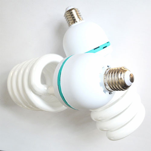 |
|
|
|
|
|
|
|
|
|
|
|
|
|
|
|
|
| Invented in 1934 by George Inman, Richard Thayer & Eugene Lemmers |
| Invented in 1934 by George Inman, Richard Thayer & Eugene Lemmers |
| Invented in 1934 by George Inman, Richard Thayer & Eugene Lemmers |
| Invented in 1934 by George Inman, Richard Thayer & Eugene Lemmers |
| Invented in 1934 by George Inman, Richard Thayer & Eugene Lemmers |
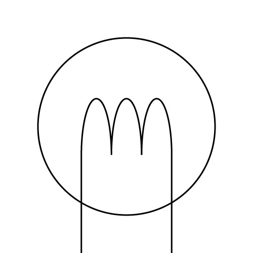 |
|
|
|
|
| Definition: To produce visible light (incandescence), a wire filament is heated to a high temperature, by providing an electric current source to a filament that is protected from oxidation with a glass or quartz bulb that is filled with inert gas or evacuated. Being non-polarised, they are used in both alternating and direct currents and are manufactured in different sizes, light output, and voltage ratings. At 800 Lumens output: An Incandescent Light Bulb of 60 watts (W) will produce 13 lumens per watt (lm/W) of light. They have a lifetime of 1,200 hours and convert 3% of their energy to visible light with 97%, 85btu’s/H expended as heat. A Compact-Fluorescent Light Bulb of 14 watts (W) will produce 57 lumens per watt (lm/W) of light. They have a lifetime of 8,000 hours and convert 66% of their energy to visible light with 34%, 30btu’s/H expended as heat. They are 29 times more efficient. An LED Light Bulb of 9 watts (W) will produce 114 lumens per watt (lm/W) of light. They have a lifetime of 50,000 hours and convert 96% of their energy to visible light with 4%, 3.4btu’s/H expended as heat. They are 365 times more efficient. |
| Definition: To produce visible light (incandescence), a wire filament is heated to a high temperature, by providing an electric current source to a filament that is protected from oxidation with a glass or quartz bulb that is filled with inert gas or evacuated. Being non-polarised, they are used in both alternating and direct currents and are manufactured in different sizes, light output, and voltage ratings. At 800 Lumens output: An Incandescent Light Bulb of 60 watts (W) will produce 13 lumens per watt (lm/W) of light. They have a lifetime of 1,200 hours and convert 3% of their energy to visible light with 97%, 85btu’s/H expended as heat. A Compact-Fluorescent Light Bulb of 14 watts (W) will produce 57 lumens per watt (lm/W) of light. They have a lifetime of 8,000 hours and convert 66% of their energy to visible light with 34%, 30btu’s/H expended as heat. They are 29 times more efficient. An LED Light Bulb of 9 watts (W) will produce 114 lumens per watt (lm/W) of light. They have a lifetime of 50,000 hours and convert 96% of their energy to visible light with 4%, 3.4btu’s/H expended as heat. They are 365 times more efficient. |
| Definition: To produce visible light (incandescence), a wire filament is heated to a high temperature, by providing an electric current source to a filament that is protected from oxidation with a glass or quartz bulb that is filled with inert gas or evacuated. Being non-polarised, they are used in both alternating and direct currents and are manufactured in different sizes, light output, and voltage ratings. At 800 Lumens output: An Incandescent Light Bulb of 60 watts (W) will produce 13 lumens per watt (lm/W) of light. They have a lifetime of 1,200 hours and convert 3% of their energy to visible light with 97%, 85btu’s/H expended as heat. A Compact-Fluorescent Light Bulb of 14 watts (W) will produce 57 lumens per watt (lm/W) of light. They have a lifetime of 8,000 hours and convert 66% of their energy to visible light with 34%, 30btu’s/H expended as heat. They are 29 times more efficient. An LED Light Bulb of 9 watts (W) will produce 114 lumens per watt (lm/W) of light. They have a lifetime of 50,000 hours and convert 96% of their energy to visible light with 4%, 3.4btu’s/H expended as heat. They are 365 times more efficient. |
| Definition: To produce visible light (incandescence), a wire filament is heated to a high temperature, by providing an electric current source to a filament that is protected from oxidation with a glass or quartz bulb that is filled with inert gas or evacuated. Being non-polarised, they are used in both alternating and direct currents and are manufactured in different sizes, light output, and voltage ratings. At 800 Lumens output: An Incandescent Light Bulb of 60 watts (W) will produce 13 lumens per watt (lm/W) of light. They have a lifetime of 1,200 hours and convert 3% of their energy to visible light with 97%, 85btu’s/H expended as heat. A Compact-Fluorescent Light Bulb of 14 watts (W) will produce 57 lumens per watt (lm/W) of light. They have a lifetime of 8,000 hours and convert 66% of their energy to visible light with 34%, 30btu’s/H expended as heat. They are 29 times more efficient. An LED Light Bulb of 9 watts (W) will produce 114 lumens per watt (lm/W) of light. They have a lifetime of 50,000 hours and convert 96% of their energy to visible light with 4%, 3.4btu’s/H expended as heat. They are 365 times more efficient. |
| Definition: To produce visible light (incandescence), a wire filament is heated to a high temperature, by providing an electric current source to a filament that is protected from oxidation with a glass or quartz bulb that is filled with inert gas or evacuated. Being non-polarised, they are used in both alternating and direct currents and are manufactured in different sizes, light output, and voltage ratings. At 800 Lumens output: An Incandescent Light Bulb of 60 watts (W) will produce 13 lumens per watt (lm/W) of light. They have a lifetime of 1,200 hours and convert 3% of their energy to visible light with 97%, 85btu’s/H expended as heat. A Compact-Fluorescent Light Bulb of 14 watts (W) will produce 57 lumens per watt (lm/W) of light. They have a lifetime of 8,000 hours and convert 66% of their energy to visible light with 34%, 30btu’s/H expended as heat. They are 29 times more efficient. An LED Light Bulb of 9 watts (W) will produce 114 lumens per watt (lm/W) of light. They have a lifetime of 50,000 hours and convert 96% of their energy to visible light with 4%, 3.4btu’s/H expended as heat. They are 365 times more efficient. |
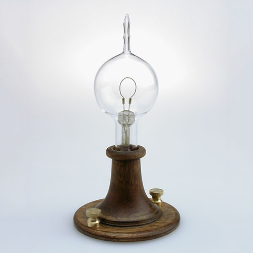 |
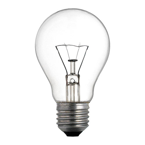 |
 |
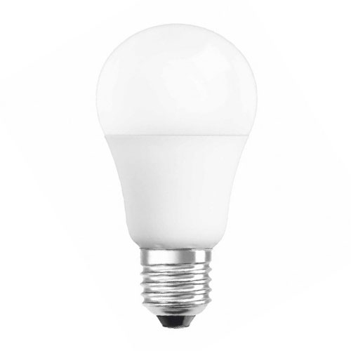 |
|
|
|
|
|
|
|
|
|
|
|
|
|
|
|
|
| Invented in 1840 by Warren de la Rue. |
| Invented in 1840 by Warren de la Rue. |
| Invented in 1840 by Warren de la Rue. |
| Invented in 1840 by Warren de la Rue. |
| Invented in 1840 by Warren de la Rue. |
| LAMP with filament of Platinum: Never patented. This is the first light bulb with an electric current passing through an enclosed coiled platinum filament in a vacuum tube. The cost of platinum made it impractical for commercial use. |
| LAMP with filament of Platinum: Never patented. This is the first light bulb with an electric current passing through an enclosed coiled platinum filament in a vacuum tube. The cost of platinum made it impractical for commercial use. |
| LAMP with filament of Platinum: Never patented. This is the first light bulb with an electric current passing through an enclosed coiled platinum filament in a vacuum tube. The cost of platinum made it impractical for commercial use. |
| LAMP with filament of Platinum: Never patented. This is the first light bulb with an electric current passing through an enclosed coiled platinum filament in a vacuum tube. The cost of platinum made it impractical for commercial use. |
| LAMP with filament of Platinum: Never patented. This is the first light bulb with an electric current passing through an enclosed coiled platinum filament in a vacuum tube. The cost of platinum made it impractical for commercial use. |
| Invented in 1840 by Warren de la Rue. |
| Invented in 1840 by Warren de la Rue. |
| Invented in 1840 by Warren de la Rue. |
| Invented in 1840 by Warren de la Rue. |
| Invented in 1840 by Warren de la Rue. |
| LAMP with filament of Carbon: Patented by John Starr and his business colleague, Edward Augustin King. Demonstrations began throughout the United States of a light bulb with a replaceable carbon strip, enclosed in a vacuum in the space above a column of mercury. Starr died after contracted tuberculosis and King was killed while serving in the American Civil War, leaving no contest to the patents of Thomas Edison. |
| LAMP with filament of Carbon: Patented by John Starr and his business colleague, Edward Augustin King. Demonstrations began throughout the United States of a light bulb with a replaceable carbon strip, enclosed in a vacuum in the space above a column of mercury. Starr died after contracted tuberculosis and King was killed while serving in the American Civil War, leaving no contest to the patents of Thomas Edison. |
| LAMP with filament of Carbon: Patented by John Starr and his business colleague, Edward Augustin King. Demonstrations began throughout the United States of a light bulb with a replaceable carbon strip, enclosed in a vacuum in the space above a column of mercury. Starr died after contracted tuberculosis and King was killed while serving in the American Civil War, leaving no contest to the patents of Thomas Edison. |
| LAMP with filament of Carbon: Patented by John Starr and his business colleague, Edward Augustin King. Demonstrations began throughout the United States of a light bulb with a replaceable carbon strip, enclosed in a vacuum in the space above a column of mercury. Starr died after contracted tuberculosis and King was killed while serving in the American Civil War, leaving no contest to the patents of Thomas Edison. |
| LAMP with filament of Carbon: Patented by John Starr and his business colleague, Edward Augustin King. Demonstrations began throughout the United States of a light bulb with a replaceable carbon strip, enclosed in a vacuum in the space above a column of mercury. Starr died after contracted tuberculosis and King was killed while serving in the American Civil War, leaving no contest to the patents of Thomas Edison. |
| Invented in 1845 by John Wellington Starr. |
| Invented in 1845 by John Wellington Starr. |
| Invented in 1845 by John Wellington Starr. |
| Invented in 1845 by John Wellington Starr. |
| Invented in 1845 by John Wellington Starr. |
| LAMP with filament of Carbon Thread: Patented two years after successful demonstration. Beginning with carbonised paper filaments in an evacuated glass bulb, further improvements ensued with a better vacuum and little residual oxygen in the vacuum tube to ignite the filament of carbonised thread, glowing white-hot without catching fire. Originally presented at a lecture in Newcastle and improvement to his original lamp, his house in Gateshead, England was the first in the world to be lit by lightbulb and additionally, the world’s first electric-light illumination in a public building was for a lecture Swan gave in 1880. In 1881, the Savoy Theatre in the City of Westminster, London, was lit by Swan incandescent lightbulbs, the first theatre and the first public building in the world to be lit entirely by electricity. He was knighted by King Edward VII in 1904. |
| LAMP with filament of Carbon Thread: Patented two years after successful demonstration. Beginning with carbonised paper filaments in an evacuated glass bulb, further improvements ensued with a better vacuum and little residual oxygen in the vacuum tube to ignite the filament of carbonised thread, glowing white-hot without catching fire. Originally presented at a lecture in Newcastle and improvement to his original lamp, his house in Gateshead, England was the first in the world to be lit by lightbulb and additionally, the world’s first electric-light illumination in a public building was for a lecture Swan gave in 1880. In 1881, the Savoy Theatre in the City of Westminster, London, was lit by Swan incandescent lightbulbs, the first theatre and the first public building in the world to be lit entirely by electricity. He was knighted by King Edward VII in 1904. |
| LAMP with filament of Carbon Thread: Patented two years after successful demonstration. Beginning with carbonised paper filaments in an evacuated glass bulb, further improvements ensued with a better vacuum and little residual oxygen in the vacuum tube to ignite the filament of carbonised thread, glowing white-hot without catching fire. Originally presented at a lecture in Newcastle and improvement to his original lamp, his house in Gateshead, England was the first in the world to be lit by lightbulb and additionally, the world’s first electric-light illumination in a public building was for a lecture Swan gave in 1880. In 1881, the Savoy Theatre in the City of Westminster, London, was lit by Swan incandescent lightbulbs, the first theatre and the first public building in the world to be lit entirely by electricity. He was knighted by King Edward VII in 1904. |
| LAMP with filament of Carbon Thread: Patented two years after successful demonstration. Beginning with carbonised paper filaments in an evacuated glass bulb, further improvements ensued with a better vacuum and little residual oxygen in the vacuum tube to ignite the filament of carbonised thread, glowing white-hot without catching fire. Originally presented at a lecture in Newcastle and improvement to his original lamp, his house in Gateshead, England was the first in the world to be lit by lightbulb and additionally, the world’s first electric-light illumination in a public building was for a lecture Swan gave in 1880. In 1881, the Savoy Theatre in the City of Westminster, London, was lit by Swan incandescent lightbulbs, the first theatre and the first public building in the world to be lit entirely by electricity. He was knighted by King Edward VII in 1904. |
| LAMP with filament of Carbon Thread: Patented two years after successful demonstration. Beginning with carbonised paper filaments in an evacuated glass bulb, further improvements ensued with a better vacuum and little residual oxygen in the vacuum tube to ignite the filament of carbonised thread, glowing white-hot without catching fire. Originally presented at a lecture in Newcastle and improvement to his original lamp, his house in Gateshead, England was the first in the world to be lit by lightbulb and additionally, the world’s first electric-light illumination in a public building was for a lecture Swan gave in 1880. In 1881, the Savoy Theatre in the City of Westminster, London, was lit by Swan incandescent lightbulbs, the first theatre and the first public building in the world to be lit entirely by electricity. He was knighted by King Edward VII in 1904. |
| Invented in 1878 by Sir Joseph Wilson Swan. |
| Invented in 1878 by Sir Joseph Wilson Swan. |
| Invented in 1878 by Sir Joseph Wilson Swan. |
| Invented in 1878 by Sir Joseph Wilson Swan. |
| Invented in 1878 by Sir Joseph Wilson Swan. |
| LAMP with filament of Bamboo: Patented. After experimenting with carbon, then platinum and other metals, in the end, Edison returned to the carbon filament with the first successful test on 22 October 1879, lasting 13.5 hours. By 4 November 1879, he filed for a US patent utilising “a carbon filament or strip coiled and connected … to platina contact wires”, several ways of creating the carbon filament including using “cotton and linen thread, wood splints, papers coiled in various ways”, he later discovered that a carbonised bamboo filament could last more than 1200 hours and in 1880, the Columbia, the first ship (steam) to use a dynamo, became the first to use the Edison’s incandescent electric lamps. |
| LAMP with filament of Bamboo: Patented. After experimenting with carbon, then platinum and other metals, in the end, Edison returned to the carbon filament with the first successful test on 22 October 1879, lasting 13.5 hours. By 4 November 1879, he filed for a US patent utilising “a carbon filament or strip coiled and connected … to platina contact wires”, several ways of creating the carbon filament including using “cotton and linen thread, wood splints, papers coiled in various ways”, he later discovered that a carbonised bamboo filament could last more than 1200 hours and in 1880, the Columbia, the first ship (steam) to use a dynamo, became the first to use the Edison’s incandescent electric lamps. |
| LAMP with filament of Bamboo: Patented. After experimenting with carbon, then platinum and other metals, in the end, Edison returned to the carbon filament with the first successful test on 22 October 1879, lasting 13.5 hours. By 4 November 1879, he filed for a US patent utilising “a carbon filament or strip coiled and connected … to platina contact wires”, several ways of creating the carbon filament including using “cotton and linen thread, wood splints, papers coiled in various ways”, he later discovered that a carbonised bamboo filament could last more than 1200 hours and in 1880, the Columbia, the first ship (steam) to use a dynamo, became the first to use the Edison’s incandescent electric lamps. |
| LAMP with filament of Bamboo: Patented. After experimenting with carbon, then platinum and other metals, in the end, Edison returned to the carbon filament with the first successful test on 22 October 1879, lasting 13.5 hours. By 4 November 1879, he filed for a US patent utilising “a carbon filament or strip coiled and connected … to platina contact wires”, several ways of creating the carbon filament including using “cotton and linen thread, wood splints, papers coiled in various ways”, he later discovered that a carbonised bamboo filament could last more than 1200 hours and in 1880, the Columbia, the first ship (steam) to use a dynamo, became the first to use the Edison’s incandescent electric lamps. |
| LAMP with filament of Bamboo: Patented. After experimenting with carbon, then platinum and other metals, in the end, Edison returned to the carbon filament with the first successful test on 22 October 1879, lasting 13.5 hours. By 4 November 1879, he filed for a US patent utilising “a carbon filament or strip coiled and connected … to platina contact wires”, several ways of creating the carbon filament including using “cotton and linen thread, wood splints, papers coiled in various ways”, he later discovered that a carbonised bamboo filament could last more than 1200 hours and in 1880, the Columbia, the first ship (steam) to use a dynamo, became the first to use the Edison’s incandescent electric lamps. |
| Invented in 1879 by Thomas Alva Edison. |
| Invented in 1879 by Thomas Alva Edison. |
| Invented in 1879 by Thomas Alva Edison. |
| Invented in 1879 by Thomas Alva Edison. |
| Invented in 1879 by Thomas Alva Edison. |
| LAMP with filament of Tungsten: This incandescent lamp used tungsten rather than carbon as a filament and became the filament standard. The intuitive process and chemistry required attracted the same competition as the incandescent lamp had received at its conception. With metallurgists combining many complicated processes from deposited layers of atomic strata to be fused, refining by heating in gases atmospheres of hydrogen and tungsten hexachloride, cooled, mixed with oxides of thorium and imbibing tungsten with organic binders, then extruding through dies, these manufacturing and chemical processes laid the foundation filaments for a duration of 100 years. |
| LAMP with filament of Tungsten: This incandescent lamp used tungsten rather than carbon as a filament and became the filament standard. The intuitive process and chemistry required attracted the same competition as the incandescent lamp had received at its conception. With metallurgists combining many complicated processes from deposited layers of atomic strata to be fused, refining by heating in gases atmospheres of hydrogen and tungsten hexachloride, cooled, mixed with oxides of thorium and imbibing tungsten with organic binders, then extruding through dies, these manufacturing and chemical processes laid the foundation filaments for a duration of 100 years. |
| LAMP with filament of Tungsten: This incandescent lamp used tungsten rather than carbon as a filament and became the filament standard. The intuitive process and chemistry required attracted the same competition as the incandescent lamp had received at its conception. With metallurgists combining many complicated processes from deposited layers of atomic strata to be fused, refining by heating in gases atmospheres of hydrogen and tungsten hexachloride, cooled, mixed with oxides of thorium and imbibing tungsten with organic binders, then extruding through dies, these manufacturing and chemical processes laid the foundation filaments for a duration of 100 years. |
| LAMP with filament of Tungsten: This incandescent lamp used tungsten rather than carbon as a filament and became the filament standard. The intuitive process and chemistry required attracted the same competition as the incandescent lamp had received at its conception. With metallurgists combining many complicated processes from deposited layers of atomic strata to be fused, refining by heating in gases atmospheres of hydrogen and tungsten hexachloride, cooled, mixed with oxides of thorium and imbibing tungsten with organic binders, then extruding through dies, these manufacturing and chemical processes laid the foundation filaments for a duration of 100 years. |
| LAMP with filament of Tungsten: This incandescent lamp used tungsten rather than carbon as a filament and became the filament standard. The intuitive process and chemistry required attracted the same competition as the incandescent lamp had received at its conception. With metallurgists combining many complicated processes from deposited layers of atomic strata to be fused, refining by heating in gases atmospheres of hydrogen and tungsten hexachloride, cooled, mixed with oxides of thorium and imbibing tungsten with organic binders, then extruding through dies, these manufacturing and chemical processes laid the foundation filaments for a duration of 100 years. |
| Invented in 1915 by Irving Languir. |
| Invented in 1915 by Irving Languir. |
| Invented in 1915 by Irving Languir. |
| Invented in 1915 by Irving Languir. |
| Invented in 1915 by Irving Languir. |
| AUDIO · COMMUNICATION · COMPUTER CONDUCTION · CONTROL · DISPLAY · ILLUMINATION MOTION · POWER · TEMPERATURE · IDENTITY |
| AUDIO · COMMUNICATION · COMPUTER CONDUCTION · CONTROL · DISPLAY · ILLUMINATION MOTION · POWER · TEMPERATURE · IDENTITY |
| AUDIO · COMMUNICATION · COMPUTER CONDUCTION · CONTROL · DISPLAY · ILLUMINATION MOTION · POWER · TEMPERATURE · IDENTITY |
| AUDIO · COMMUNICATION · COMPUTER CONDUCTION · CONTROL · DISPLAY · ILLUMINATION MOTION · POWER · TEMPERATURE · IDENTITY |
| AUDIO · COMMUNICATION · COMPUTER CONDUCTION · CONTROL · DISPLAY · ILLUMINATION MOTION · POWER · TEMPERATURE · IDENTITY |
 |
|
|
|
|
| Definition: Forming components of inertial navigation systems for aircraft and missiles, these devices are used to detect and monitor vibration in rotating machinery, screen orientation for computers devices and additionally for stabilisation for imagery, air and space craft. Measuring proper acceleration, g-force, is different from coordinate acceleration, change rate of velocity. An accelerometer on the surface of the Earth will measure an acceleration g= 9.81 m/s2 straight up, yet a free fall from orbit will measure zero. |
| Definition: Forming components of inertial navigation systems for aircraft and missiles, these devices are used to detect and monitor vibration in rotating machinery, screen orientation for computers devices and additionally for stabilisation for imagery, air and space craft. Measuring proper acceleration, g-force, is different from coordinate acceleration, change rate of velocity. An accelerometer on the surface of the Earth will measure an acceleration g= 9.81 m/s2 straight up, yet a free fall from orbit will measure zero. |
| Definition: Forming components of inertial navigation systems for aircraft and missiles, these devices are used to detect and monitor vibration in rotating machinery, screen orientation for computers devices and additionally for stabilisation for imagery, air and space craft. Measuring proper acceleration, g-force, is different from coordinate acceleration, change rate of velocity. An accelerometer on the surface of the Earth will measure an acceleration g= 9.81 m/s2 straight up, yet a free fall from orbit will measure zero. |
| Definition: Forming components of inertial navigation systems for aircraft and missiles, these devices are used to detect and monitor vibration in rotating machinery, screen orientation for computers devices and additionally for stabilisation for imagery, air and space craft. Measuring proper acceleration, g-force, is different from coordinate acceleration, change rate of velocity. An accelerometer on the surface of the Earth will measure an acceleration g= 9.81 m/s2 straight up, yet a free fall from orbit will measure zero. |
| Definition: Forming components of inertial navigation systems for aircraft and missiles, these devices are used to detect and monitor vibration in rotating machinery, screen orientation for computers devices and additionally for stabilisation for imagery, air and space craft. Measuring proper acceleration, g-force, is different from coordinate acceleration, change rate of velocity. An accelerometer on the surface of the Earth will measure an acceleration g= 9.81 m/s2 straight up, yet a free fall from orbit will measure zero. |
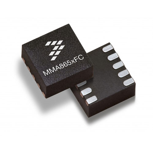 |
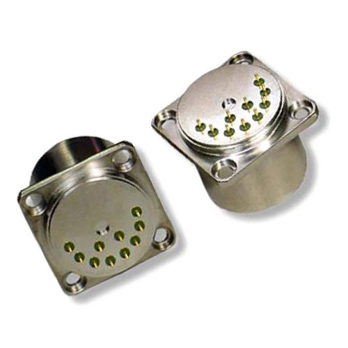 |
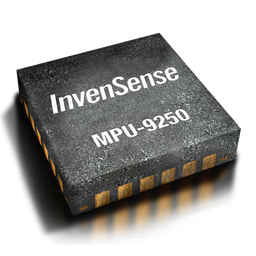 |
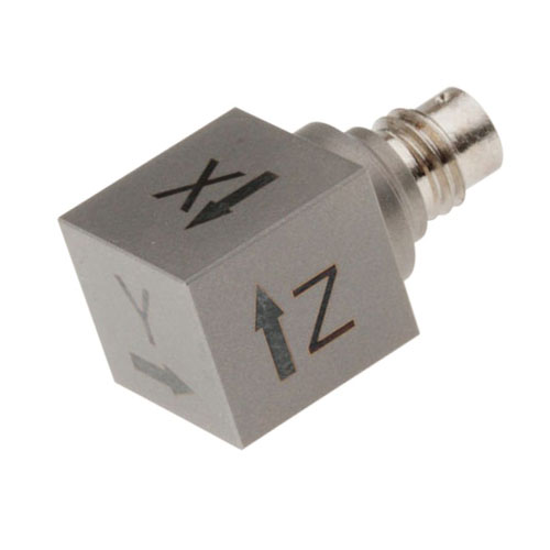 |
|
|
|
|
|
|
|
|
|
|
|
|
|
|
|
|
| Invented in 1783 by George Atwood. |
| Invented in 1783 by George Atwood. |
| Invented in 1783 by George Atwood. |
| Invented in 1783 by George Atwood. |
| Invented in 1783 by George Atwood. |
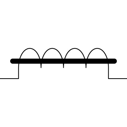 |
|
|
|
|
| Definition: Electromagnets are coils of closely spaced turns of wire surrounding a magnetic core. Magnetism is generated by controlling the amount and direction of electric current induced in the windings. They are used within MRI machines, motors, generators, relays, loudspeakers, solenoids and hard disks. |
| Definition: Electromagnets are coils of closely spaced turns of wire surrounding a magnetic core. Magnetism is generated by controlling the amount and direction of electric current induced in the windings. They are used within MRI machines, motors, generators, relays, loudspeakers, solenoids and hard disks. |
| Definition: Electromagnets are coils of closely spaced turns of wire surrounding a magnetic core. Magnetism is generated by controlling the amount and direction of electric current induced in the windings. They are used within MRI machines, motors, generators, relays, loudspeakers, solenoids and hard disks. |
| Definition: Electromagnets are coils of closely spaced turns of wire surrounding a magnetic core. Magnetism is generated by controlling the amount and direction of electric current induced in the windings. They are used within MRI machines, motors, generators, relays, loudspeakers, solenoids and hard disks. |
| Definition: Electromagnets are coils of closely spaced turns of wire surrounding a magnetic core. Magnetism is generated by controlling the amount and direction of electric current induced in the windings. They are used within MRI machines, motors, generators, relays, loudspeakers, solenoids and hard disks. |
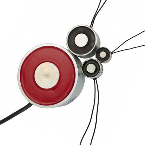 |
 |
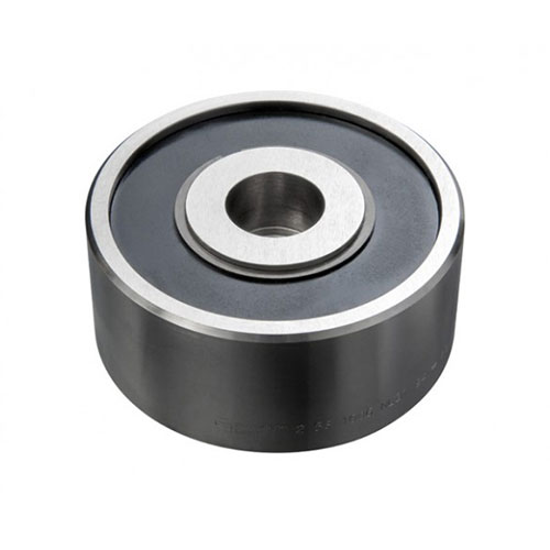 |
 |
|
|
|
|
|
|
|
|
|
|
|
|
|
|
|
|
| Invented in 1821 by Hans Christian Ørsted. |
| Invented in 1821 by Hans Christian Ørsted. |
| Invented in 1821 by Hans Christian Ørsted. |
| Invented in 1821 by Hans Christian Ørsted. |
| Invented in 1821 by Hans Christian Ørsted. |
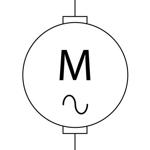 AC |
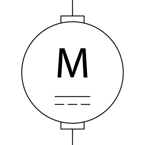 DC |
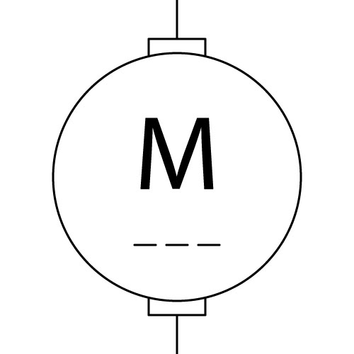 Stepper |
AC |
DC |
Stepper |
AC |
DC |
Stepper |
AC |
DC |
Stepper |
AC |
DC |
Stepper |
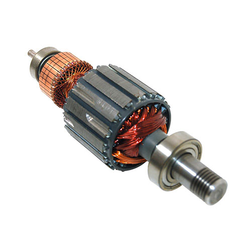 Armature |
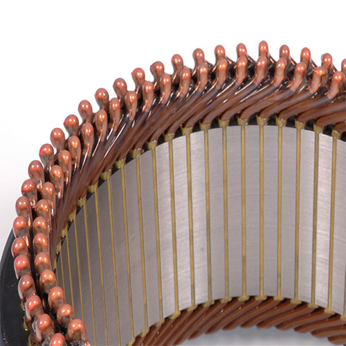 Stator |
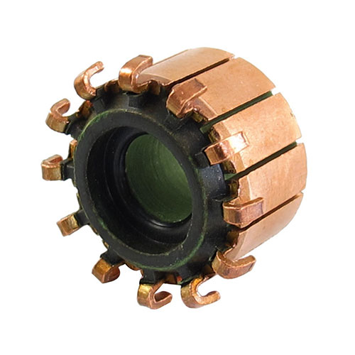 Commutator |
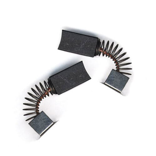 Brushes |
Armature |
Stator |
Commutator |
Brushes |
Armature |
Stator |
Commutator |
Brushes |
Armature |
Stator |
Commutator |
Brushes |
Armature |
Stator |
Commutator |
Brushes |
| Definition: An electric motor is an electrical machine that converts electrical energy into mechanical energy and operate through the interaction between an electric motor’s magnetic field and winding currents to generate force within AC, DC and Pulsed DC motors. Armature: A component of a motor or generator with a role to: carry current crossing the field, thus creating shaft torque in a rotating machine or force in a linear machine; to generate an electromotive force (EMF) and to produce a rotating magnet field to pull or push the rotor assembly and as a result, produce work. Brushes: Mostly used in rotating shafts, a brush conducts current between stationary wires and moving components, as with electric motors, alternators or generators. Commutator: This is part of an electric motor or generator that is made up of a cylinder of insulated metal bars connected to armature coils that is fixed to a shaft on bearings. The commutator is energised by being in contact with graphite brushes. |
| Definition: An electric motor is an electrical machine that converts electrical energy into mechanical energy and operate through the interaction between an electric motor’s magnetic field and winding currents to generate force within AC, DC and Pulsed DC motors. Armature: A component of a motor or generator with a role to: carry current crossing the field, thus creating shaft torque in a rotating machine or force in a linear machine; to generate an electromotive force (EMF) and to produce a rotating magnet field to pull or push the rotor assembly and as a result, produce work. Brushes: Mostly used in rotating shafts, a brush conducts current between stationary wires and moving components, as with electric motors, alternators or generators. Commutator: This is part of an electric motor or generator that is made up of a cylinder of insulated metal bars connected to armature coils that is fixed to a shaft on bearings. The commutator is energised by being in contact with graphite brushes. |
| Definition: An electric motor is an electrical machine that converts electrical energy into mechanical energy and operate through the interaction between an electric motor’s magnetic field and winding currents to generate force within AC, DC and Pulsed DC motors. Armature: A component of a motor or generator with a role to: carry current crossing the field, thus creating shaft torque in a rotating machine or force in a linear machine; to generate an electromotive force (EMF) and to produce a rotating magnet field to pull or push the rotor assembly and as a result, produce work. Brushes: Mostly used in rotating shafts, a brush conducts current between stationary wires and moving components, as with electric motors, alternators or generators. Commutator: This is part of an electric motor or generator that is made up of a cylinder of insulated metal bars connected to armature coils that is fixed to a shaft on bearings. The commutator is energised by being in contact with graphite brushes. |
| Definition: An electric motor is an electrical machine that converts electrical energy into mechanical energy and operate through the interaction between an electric motor’s magnetic field and winding currents to generate force within AC, DC and Pulsed DC motors. Armature: A component of a motor or generator with a role to: carry current crossing the field, thus creating shaft torque in a rotating machine or force in a linear machine; to generate an electromotive force (EMF) and to produce a rotating magnet field to pull or push the rotor assembly and as a result, produce work. Brushes: Mostly used in rotating shafts, a brush conducts current between stationary wires and moving components, as with electric motors, alternators or generators. Commutator: This is part of an electric motor or generator that is made up of a cylinder of insulated metal bars connected to armature coils that is fixed to a shaft on bearings. The commutator is energised by being in contact with graphite brushes. |
| Definition: An electric motor is an electrical machine that converts electrical energy into mechanical energy and operate through the interaction between an electric motor’s magnetic field and winding currents to generate force within AC, DC and Pulsed DC motors. Armature: A component of a motor or generator with a role to: carry current crossing the field, thus creating shaft torque in a rotating machine or force in a linear machine; to generate an electromotive force (EMF) and to produce a rotating magnet field to pull or push the rotor assembly and as a result, produce work. Brushes: Mostly used in rotating shafts, a brush conducts current between stationary wires and moving components, as with electric motors, alternators or generators. Commutator: This is part of an electric motor or generator that is made up of a cylinder of insulated metal bars connected to armature coils that is fixed to a shaft on bearings. The commutator is energised by being in contact with graphite brushes. |
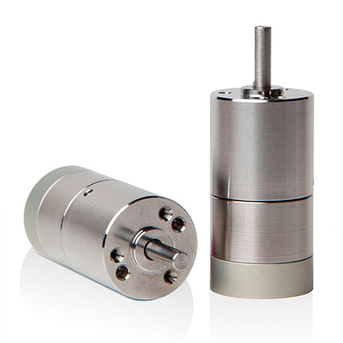 |
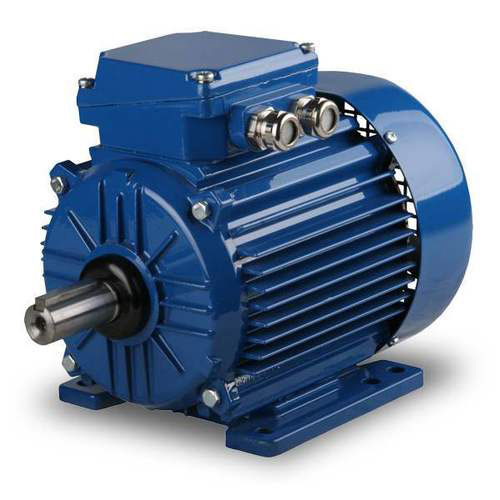 |
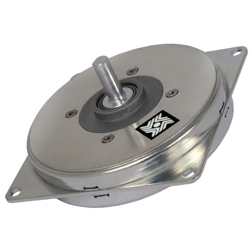 |
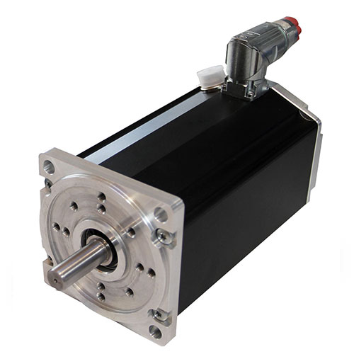 |
|
|
|
|
|
|
|
|
|
|
|
|
|
|
|
|
| Invented in 1834 by Moritz von Jacobi. |
| Invented in 1834 by Moritz von Jacobi. |
| Invented in 1834 by Moritz von Jacobi. |
| Invented in 1834 by Moritz von Jacobi. |
| Invented in 1834 by Moritz von Jacobi. |
 |
|
|
|
|
| Definition: Electromechanical device that use electromagnetism to produce a linear mechanical force. The variety of these transducer devices span from electromechanical solenoids which actuate pneumatic or hydraulic valves, solenoid switch internally uses an electromechanical solenoid to operate an electrical switch; or a linear solenoid, which is an electromechanical locking mechanism. |
| Definition: Electromechanical device that use electromagnetism to produce a linear mechanical force. The variety of these transducer devices span from electromechanical solenoids which actuate pneumatic or hydraulic valves, solenoid switch internally uses an electromechanical solenoid to operate an electrical switch; or a linear solenoid, which is an electromechanical locking mechanism. |
| Definition: Electromechanical device that use electromagnetism to produce a linear mechanical force. The variety of these transducer devices span from electromechanical solenoids which actuate pneumatic or hydraulic valves, solenoid switch internally uses an electromechanical solenoid to operate an electrical switch; or a linear solenoid, which is an electromechanical locking mechanism. |
| Definition: Electromechanical device that use electromagnetism to produce a linear mechanical force. The variety of these transducer devices span from electromechanical solenoids which actuate pneumatic or hydraulic valves, solenoid switch internally uses an electromechanical solenoid to operate an electrical switch; or a linear solenoid, which is an electromechanical locking mechanism. |
| Definition: Electromechanical device that use electromagnetism to produce a linear mechanical force. The variety of these transducer devices span from electromechanical solenoids which actuate pneumatic or hydraulic valves, solenoid switch internally uses an electromechanical solenoid to operate an electrical switch; or a linear solenoid, which is an electromechanical locking mechanism. |
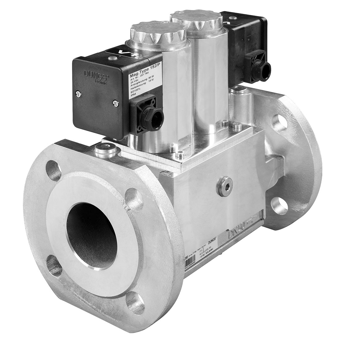 |
 |
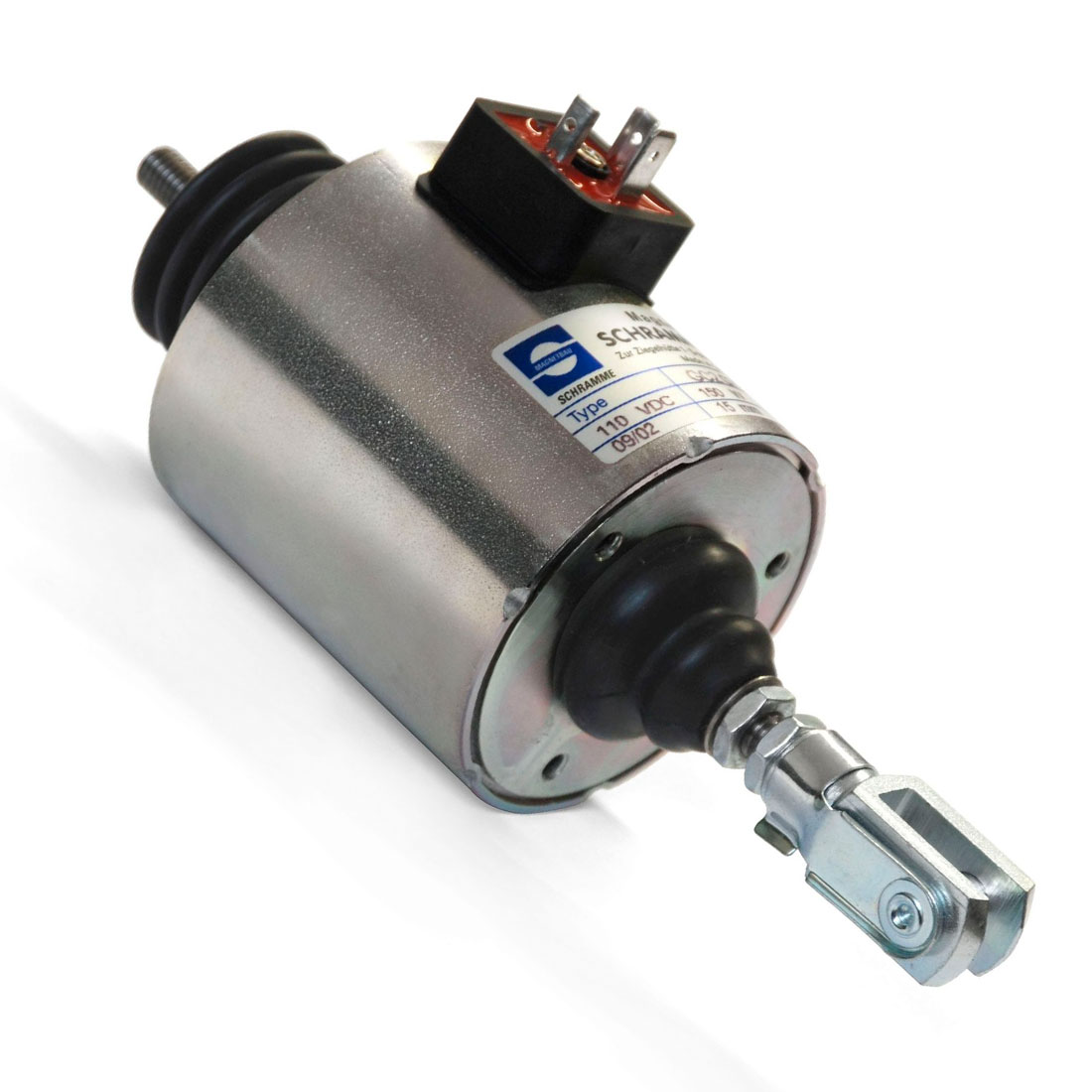 |
 |
|
|
|
|
|
|
|
|
|
|
|
|
|
|
|
|
| Invented in 1838 by Charles Grafton Page. |
| Invented in 1838 by Charles Grafton Page. |
| Invented in 1838 by Charles Grafton Page. |
| Invented in 1838 by Charles Grafton Page. |
| Invented in 1838 by Charles Grafton Page. |
| AUDIO · COMMUNICATION · COMPUTER CONDUCTION · CONTROL · DISPLAY · ILLUMINATION MOTION · POWER · TEMPERATURE · IDENTITY |
| AUDIO · COMMUNICATION · COMPUTER CONDUCTION · CONTROL · DISPLAY · ILLUMINATION MOTION · POWER · TEMPERATURE · IDENTITY |
| AUDIO · COMMUNICATION · COMPUTER CONDUCTION · CONTROL · DISPLAY · ILLUMINATION MOTION · POWER · TEMPERATURE · IDENTITY |
| AUDIO · COMMUNICATION · COMPUTER CONDUCTION · CONTROL · DISPLAY · ILLUMINATION MOTION · POWER · TEMPERATURE · IDENTITY |
| AUDIO · COMMUNICATION · COMPUTER CONDUCTION · CONTROL · DISPLAY · ILLUMINATION MOTION · POWER · TEMPERATURE · IDENTITY |
 |
|
|
|
|
| Definition: An alternator is an electromechanical device which converts mechanical energy to electrical energy in the form of Alternating Current at a given Voltage, Current and Frequency. The Alternator, as with the Generator, Dynamo and Motor, are Electromechanical Devices with a Rotor (rotating component) and Stator (stationary component) with Brushes and Commutator (cylindrical copper segments) that are used to carry current to and from a Rotor. The Armature, can be either a Rotor or a Stator and is an Electromagnetic Conductive Coil that is inductively coupled to the Field. The Field, can be either a Rotor or a Stator and is a Magnet or Electromagnet that is inductively coupled to an Armature. The rotating magnetic field of the Rotor moving relative to a magnetic field of the Stator, developing an electromotive force (EMF) that reverses as it moves under the magnetic poles of opposing polarity, inducing an AC voltage in the stator windings. By displacing multiple sets of stator windings, a multitude of AC currents, including 3 phase current, is created. Output frequency is dependent on rotational speed of the Rotor and the number of poles, as one cycle of alternating current is created when field pole pairs pass over a stationary winding. For greater current carrying capacities, the Armature as a Stator is the preferred manufacture method. |
| Definition: An alternator is an electromechanical device which converts mechanical energy to electrical energy in the form of Alternating Current at a given Voltage, Current and Frequency. The Alternator, as with the Generator, Dynamo and Motor, are Electromechanical Devices with a Rotor (rotating component) and Stator (stationary component) with Brushes and Commutator (cylindrical copper segments) that are used to carry current to and from a Rotor. The Armature, can be either a Rotor or a Stator and is an Electromagnetic Conductive Coil that is inductively coupled to the Field. The Field, can be either a Rotor or a Stator and is a Magnet or Electromagnet that is inductively coupled to an Armature. The rotating magnetic field of the Rotor moving relative to a magnetic field of the Stator, developing an electromotive force (EMF) that reverses as it moves under the magnetic poles of opposing polarity, inducing an AC voltage in the stator windings. By displacing multiple sets of stator windings, a multitude of AC currents, including 3 phase current, is created. Output frequency is dependent on rotational speed of the Rotor and the number of poles, as one cycle of alternating current is created when field pole pairs pass over a stationary winding. For greater current carrying capacities, the Armature as a Stator is the preferred manufacture method. |
| Definition: An alternator is an electromechanical device which converts mechanical energy to electrical energy in the form of Alternating Current at a given Voltage, Current and Frequency. The Alternator, as with the Generator, Dynamo and Motor, are Electromechanical Devices with a Rotor (rotating component) and Stator (stationary component) with Brushes and Commutator (cylindrical copper segments) that are used to carry current to and from a Rotor. The Armature, can be either a Rotor or a Stator and is an Electromagnetic Conductive Coil that is inductively coupled to the Field. The Field, can be either a Rotor or a Stator and is a Magnet or Electromagnet that is inductively coupled to an Armature. The rotating magnetic field of the Rotor moving relative to a magnetic field of the Stator, developing an electromotive force (EMF) that reverses as it moves under the magnetic poles of opposing polarity, inducing an AC voltage in the stator windings. By displacing multiple sets of stator windings, a multitude of AC currents, including 3 phase current, is created. Output frequency is dependent on rotational speed of the Rotor and the number of poles, as one cycle of alternating current is created when field pole pairs pass over a stationary winding. For greater current carrying capacities, the Armature as a Stator is the preferred manufacture method. |
| Definition: An alternator is an electromechanical device which converts mechanical energy to electrical energy in the form of Alternating Current at a given Voltage, Current and Frequency. The Alternator, as with the Generator, Dynamo and Motor, are Electromechanical Devices with a Rotor (rotating component) and Stator (stationary component) with Brushes and Commutator (cylindrical copper segments) that are used to carry current to and from a Rotor. The Armature, can be either a Rotor or a Stator and is an Electromagnetic Conductive Coil that is inductively coupled to the Field. The Field, can be either a Rotor or a Stator and is a Magnet or Electromagnet that is inductively coupled to an Armature. The rotating magnetic field of the Rotor moving relative to a magnetic field of the Stator, developing an electromotive force (EMF) that reverses as it moves under the magnetic poles of opposing polarity, inducing an AC voltage in the stator windings. By displacing multiple sets of stator windings, a multitude of AC currents, including 3 phase current, is created. Output frequency is dependent on rotational speed of the Rotor and the number of poles, as one cycle of alternating current is created when field pole pairs pass over a stationary winding. For greater current carrying capacities, the Armature as a Stator is the preferred manufacture method. |
| Definition: An alternator is an electromechanical device which converts mechanical energy to electrical energy in the form of Alternating Current at a given Voltage, Current and Frequency. The Alternator, as with the Generator, Dynamo and Motor, are Electromechanical Devices with a Rotor (rotating component) and Stator (stationary component) with Brushes and Commutator (cylindrical copper segments) that are used to carry current to and from a Rotor. The Armature, can be either a Rotor or a Stator and is an Electromagnetic Conductive Coil that is inductively coupled to the Field. The Field, can be either a Rotor or a Stator and is a Magnet or Electromagnet that is inductively coupled to an Armature. The rotating magnetic field of the Rotor moving relative to a magnetic field of the Stator, developing an electromotive force (EMF) that reverses as it moves under the magnetic poles of opposing polarity, inducing an AC voltage in the stator windings. By displacing multiple sets of stator windings, a multitude of AC currents, including 3 phase current, is created. Output frequency is dependent on rotational speed of the Rotor and the number of poles, as one cycle of alternating current is created when field pole pairs pass over a stationary winding. For greater current carrying capacities, the Armature as a Stator is the preferred manufacture method. |
 |
 |
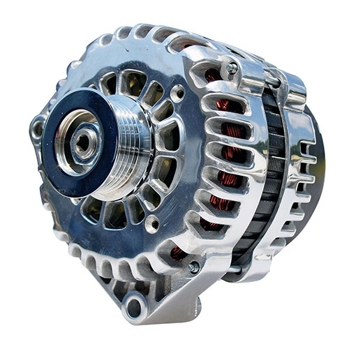 |
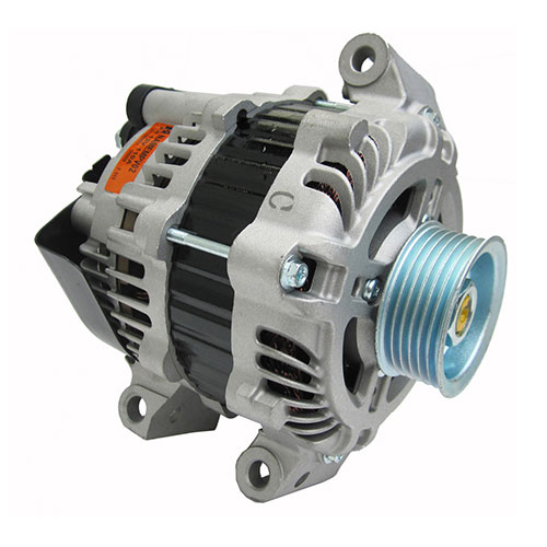 |
|
|
|
|
|
|
|
|
|
|
|
|
|
|
|
|
| Invented in 1831 by Michael Faraday. |
| Invented in 1831 by Michael Faraday. |
| Invented in 1831 by Michael Faraday. |
| Invented in 1831 by Michael Faraday. |
| Invented in 1831 by Michael Faraday. |
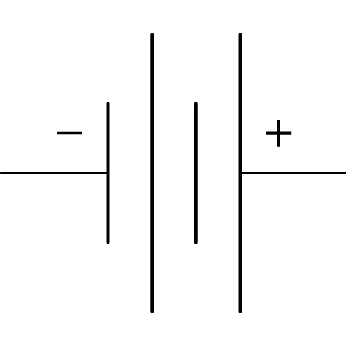 |
|
|
|
|
| Definition: There are two main classes of batteries: “Primary Cells” non-rechargeable batteries include: Alkaline, Dry cell, Mercury to Atomic Betavoltaics, Optoelectric or Nuclear. “Secondary Cells” rechargeable batteries include: Lead–acid, Lithium-ion, Nickel metal hydride, Super iron to Fuel cells. |
| Definition: There are two main classes of batteries: “Primary Cells” non-rechargeable batteries include: Alkaline, Dry cell, Mercury to Atomic Betavoltaics, Optoelectric or Nuclear. “Secondary Cells” rechargeable batteries include: Lead–acid, Lithium-ion, Nickel metal hydride, Super iron to Fuel cells. |
| Definition: There are two main classes of batteries: “Primary Cells” non-rechargeable batteries include: Alkaline, Dry cell, Mercury to Atomic Betavoltaics, Optoelectric or Nuclear. “Secondary Cells” rechargeable batteries include: Lead–acid, Lithium-ion, Nickel metal hydride, Super iron to Fuel cells. |
| Definition: There are two main classes of batteries: “Primary Cells” non-rechargeable batteries include: Alkaline, Dry cell, Mercury to Atomic Betavoltaics, Optoelectric or Nuclear. “Secondary Cells” rechargeable batteries include: Lead–acid, Lithium-ion, Nickel metal hydride, Super iron to Fuel cells. |
| Definition: There are two main classes of batteries: “Primary Cells” non-rechargeable batteries include: Alkaline, Dry cell, Mercury to Atomic Betavoltaics, Optoelectric or Nuclear. “Secondary Cells” rechargeable batteries include: Lead–acid, Lithium-ion, Nickel metal hydride, Super iron to Fuel cells. |
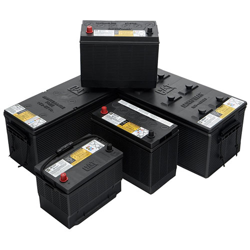 |
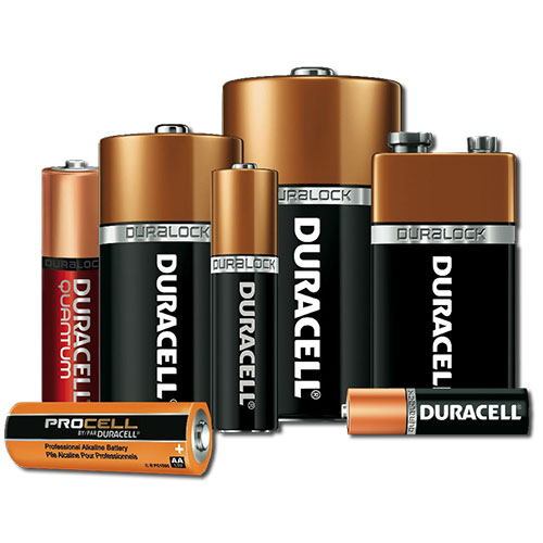 |
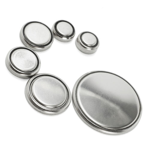 |
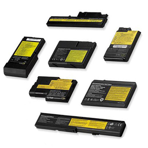 |
|
|
|
|
|
|
|
|
|
|
|
|
|
|
|
|
| Invented in 1799 by Allessandro Volta. |
| Invented in 1799 by Allessandro Volta. |
| Invented in 1799 by Allessandro Volta. |
| Invented in 1799 by Allessandro Volta. |
| Invented in 1799 by Allessandro Volta. |
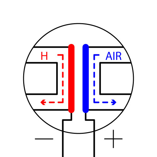 |
|
|
|
|
| Definition: Fuel cells convert chemical energy into electricity, through an electrochemical reaction of hydrogen fuel with oxygen and are currently used to generate power for satellites, spacecraft, buildings, forklifts, automobiles, buses, boats, motorcycles, and submarines. All fuel cells consist of an anode, a cathode, and an electrolyte, to allow positively charged hydrogen ions (protons) to move between both sides of a fuel cell. A catalyst is introduced to the Anode, to cause oxidation reactions and to generate protons (positively charged hydrogen ions) and electrons, with protons flowing from the anode to the cathode through the electrolyte, after the reaction. Simultaneously, electrons travel from the anode to the cathode through an external circuit, producing direct current electricity. Another catalyst is introduced at the cathode, to cause of hydrogen ions, electrons, and oxygen to form water. |
| Definition: Fuel cells convert chemical energy into electricity, through an electrochemical reaction of hydrogen fuel with oxygen and are currently used to generate power for satellites, spacecraft, buildings, forklifts, automobiles, buses, boats, motorcycles, and submarines. All fuel cells consist of an anode, a cathode, and an electrolyte, to allow positively charged hydrogen ions (protons) to move between both sides of a fuel cell. A catalyst is introduced to the Anode, to cause oxidation reactions and to generate protons (positively charged hydrogen ions) and electrons, with protons flowing from the anode to the cathode through the electrolyte, after the reaction. Simultaneously, electrons travel from the anode to the cathode through an external circuit, producing direct current electricity. Another catalyst is introduced at the cathode, to cause of hydrogen ions, electrons, and oxygen to form water. |
| Definition: Fuel cells convert chemical energy into electricity, through an electrochemical reaction of hydrogen fuel with oxygen and are currently used to generate power for satellites, spacecraft, buildings, forklifts, automobiles, buses, boats, motorcycles, and submarines. All fuel cells consist of an anode, a cathode, and an electrolyte, to allow positively charged hydrogen ions (protons) to move between both sides of a fuel cell. A catalyst is introduced to the Anode, to cause oxidation reactions and to generate protons (positively charged hydrogen ions) and electrons, with protons flowing from the anode to the cathode through the electrolyte, after the reaction. Simultaneously, electrons travel from the anode to the cathode through an external circuit, producing direct current electricity. Another catalyst is introduced at the cathode, to cause of hydrogen ions, electrons, and oxygen to form water. |
| Definition: Fuel cells convert chemical energy into electricity, through an electrochemical reaction of hydrogen fuel with oxygen and are currently used to generate power for satellites, spacecraft, buildings, forklifts, automobiles, buses, boats, motorcycles, and submarines. All fuel cells consist of an anode, a cathode, and an electrolyte, to allow positively charged hydrogen ions (protons) to move between both sides of a fuel cell. A catalyst is introduced to the Anode, to cause oxidation reactions and to generate protons (positively charged hydrogen ions) and electrons, with protons flowing from the anode to the cathode through the electrolyte, after the reaction. Simultaneously, electrons travel from the anode to the cathode through an external circuit, producing direct current electricity. Another catalyst is introduced at the cathode, to cause of hydrogen ions, electrons, and oxygen to form water. |
| Definition: Fuel cells convert chemical energy into electricity, through an electrochemical reaction of hydrogen fuel with oxygen and are currently used to generate power for satellites, spacecraft, buildings, forklifts, automobiles, buses, boats, motorcycles, and submarines. All fuel cells consist of an anode, a cathode, and an electrolyte, to allow positively charged hydrogen ions (protons) to move between both sides of a fuel cell. A catalyst is introduced to the Anode, to cause oxidation reactions and to generate protons (positively charged hydrogen ions) and electrons, with protons flowing from the anode to the cathode through the electrolyte, after the reaction. Simultaneously, electrons travel from the anode to the cathode through an external circuit, producing direct current electricity. Another catalyst is introduced at the cathode, to cause of hydrogen ions, electrons, and oxygen to form water. |
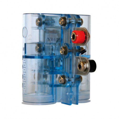 |
 |
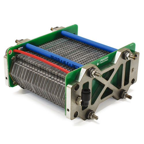 |
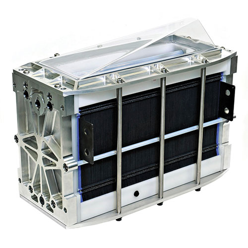 |
|
|
|
|
|
|
|
|
|
|
|
|
|
|
|
|
| Invented in 1838 by William Robert Grove. |
| Invented in 1838 by William Robert Grove. |
| Invented in 1838 by William Robert Grove. |
| Invented in 1838 by William Robert Grove. |
| Invented in 1838 by William Robert Grove. |
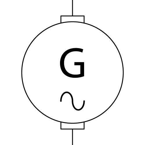 |
|
|
|
|
| Definition: Alternating Current Generators began with the discovery of Michael Faraday regarding the magnetic induction of electric current, with a heteropolar “rotating rectangle”, with active conductors passing through opposing magnetic fields and forming the basis of multiphase alternating current generators, first built by a British electrician, James Edward Henry Gordon in 1882. |
| Definition: Alternating Current Generators began with the discovery of Michael Faraday regarding the magnetic induction of electric current, with a heteropolar “rotating rectangle”, with active conductors passing through opposing magnetic fields and forming the basis of multiphase alternating current generators, first built by a British electrician, James Edward Henry Gordon in 1882. |
| Definition: Alternating Current Generators began with the discovery of Michael Faraday regarding the magnetic induction of electric current, with a heteropolar “rotating rectangle”, with active conductors passing through opposing magnetic fields and forming the basis of multiphase alternating current generators, first built by a British electrician, James Edward Henry Gordon in 1882. |
| Definition: Alternating Current Generators began with the discovery of Michael Faraday regarding the magnetic induction of electric current, with a heteropolar “rotating rectangle”, with active conductors passing through opposing magnetic fields and forming the basis of multiphase alternating current generators, first built by a British electrician, James Edward Henry Gordon in 1882. |
| Definition: Alternating Current Generators began with the discovery of Michael Faraday regarding the magnetic induction of electric current, with a heteropolar “rotating rectangle”, with active conductors passing through opposing magnetic fields and forming the basis of multiphase alternating current generators, first built by a British electrician, James Edward Henry Gordon in 1882. |
 |
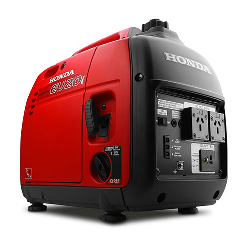 |
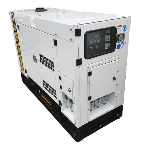 |
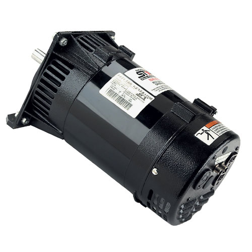 |
|
|
|
|
|
|
|
|
|
|
|
|
|
|
|
|
| Invented in 1830 by Michael Faraday. |
| Invented in 1830 by Michael Faraday. |
| Invented in 1830 by Michael Faraday. |
| Invented in 1830 by Michael Faraday. |
| Invented in 1830 by Michael Faraday. |
 |
|
|
|
|
| Definition: The Faraday disk generator is the first electric direct current homopolar generator, with a horseshoe-shaped magnet creating a magnetic field through a copper disk, that when rotated, induced an electric current radially outward, toward the rim. Current passed through a sliding spring contact, through an external circuit, then back through the axle. |
| Definition: The Faraday disk generator is the first electric direct current homopolar generator, with a horseshoe-shaped magnet creating a magnetic field through a copper disk, that when rotated, induced an electric current radially outward, toward the rim. Current passed through a sliding spring contact, through an external circuit, then back through the axle. |
| Definition: The Faraday disk generator is the first electric direct current homopolar generator, with a horseshoe-shaped magnet creating a magnetic field through a copper disk, that when rotated, induced an electric current radially outward, toward the rim. Current passed through a sliding spring contact, through an external circuit, then back through the axle. |
| Definition: The Faraday disk generator is the first electric direct current homopolar generator, with a horseshoe-shaped magnet creating a magnetic field through a copper disk, that when rotated, induced an electric current radially outward, toward the rim. Current passed through a sliding spring contact, through an external circuit, then back through the axle. |
| Definition: The Faraday disk generator is the first electric direct current homopolar generator, with a horseshoe-shaped magnet creating a magnetic field through a copper disk, that when rotated, induced an electric current radially outward, toward the rim. Current passed through a sliding spring contact, through an external circuit, then back through the axle. |
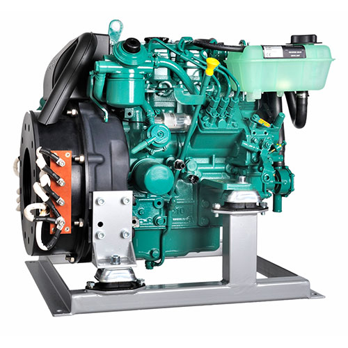 |
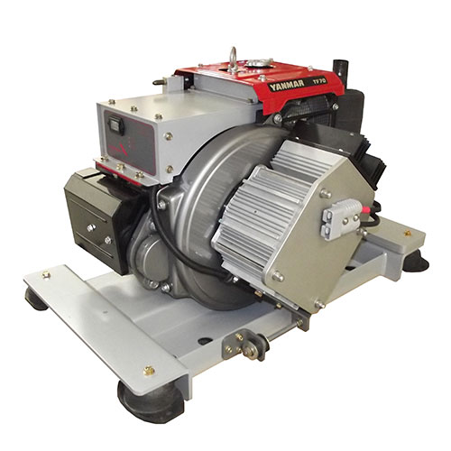 |
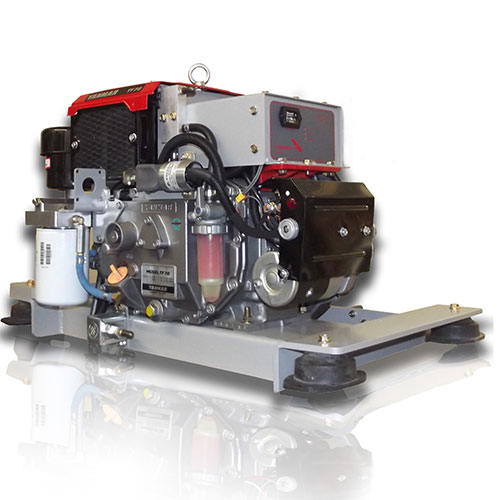 |
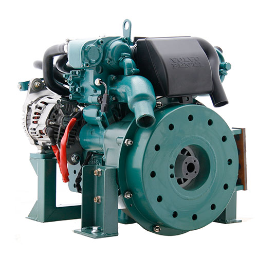 |
|
|
|
|
|
|
|
|
|
|
|
|
|
|
|
|
| Invented in 1830 by Michael Faraday. |
| Invented in 1830 by Michael Faraday. |
| Invented in 1830 by Michael Faraday. |
| Invented in 1830 by Michael Faraday. |
| Invented in 1830 by Michael Faraday. |
| Generator, Piezoelectric |
| Generator, Piezoelectric |
| Generator, Piezoelectric |
| Generator, Piezoelectric |
| Generator, Piezoelectric |
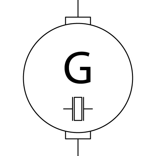 |
|
|
|
|
| Definition: Piezoelectricity is the accumulation of electricity in solid materials, such as crystals and ceramics, which can be released by pressure or heat and is best understood as the linear electromechanical interaction between the mechanical and the electrical state of crystalline materials, with no inversion symmetry and a reversible process in materials exhibiting this effect. Lead zirconate titanate crystals will generate measurable piezoelectricity when their static structure is deformed to 0.1% of the original symmetry. Conversely, these crystals change to 0.1% of their static dimension when an external electric field is applied to this material. |
| Definition: Piezoelectricity is the accumulation of electricity in solid materials, such as crystals and ceramics, which can be released by pressure or heat and is best understood as the linear electromechanical interaction between the mechanical and the electrical state of crystalline materials, with no inversion symmetry and a reversible process in materials exhibiting this effect. Lead zirconate titanate crystals will generate measurable piezoelectricity when their static structure is deformed to 0.1% of the original symmetry. Conversely, these crystals change to 0.1% of their static dimension when an external electric field is applied to this material. |
| Definition: Piezoelectricity is the accumulation of electricity in solid materials, such as crystals and ceramics, which can be released by pressure or heat and is best understood as the linear electromechanical interaction between the mechanical and the electrical state of crystalline materials, with no inversion symmetry and a reversible process in materials exhibiting this effect. Lead zirconate titanate crystals will generate measurable piezoelectricity when their static structure is deformed to 0.1% of the original symmetry. Conversely, these crystals change to 0.1% of their static dimension when an external electric field is applied to this material. |
| Definition: Piezoelectricity is the accumulation of electricity in solid materials, such as crystals and ceramics, which can be released by pressure or heat and is best understood as the linear electromechanical interaction between the mechanical and the electrical state of crystalline materials, with no inversion symmetry and a reversible process in materials exhibiting this effect. Lead zirconate titanate crystals will generate measurable piezoelectricity when their static structure is deformed to 0.1% of the original symmetry. Conversely, these crystals change to 0.1% of their static dimension when an external electric field is applied to this material. |
| Definition: Piezoelectricity is the accumulation of electricity in solid materials, such as crystals and ceramics, which can be released by pressure or heat and is best understood as the linear electromechanical interaction between the mechanical and the electrical state of crystalline materials, with no inversion symmetry and a reversible process in materials exhibiting this effect. Lead zirconate titanate crystals will generate measurable piezoelectricity when their static structure is deformed to 0.1% of the original symmetry. Conversely, these crystals change to 0.1% of their static dimension when an external electric field is applied to this material. |
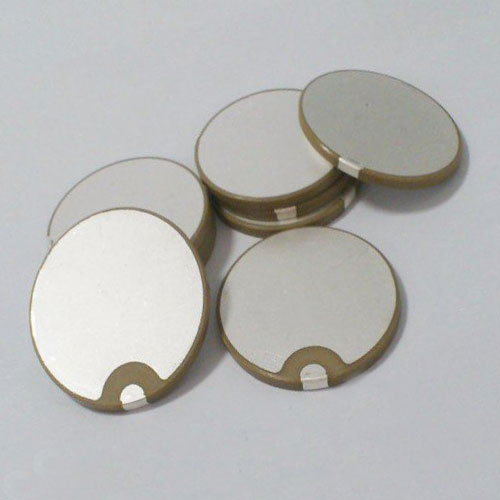 |
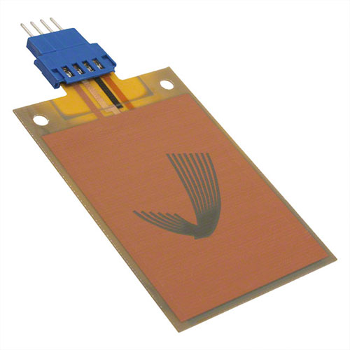 |
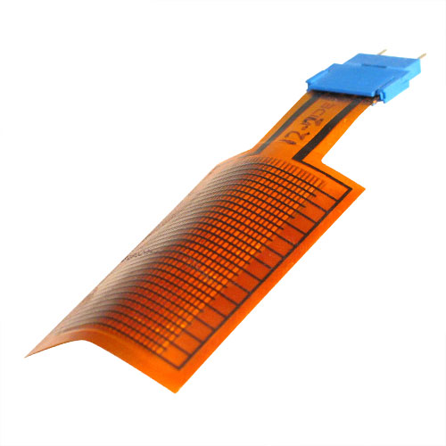 |
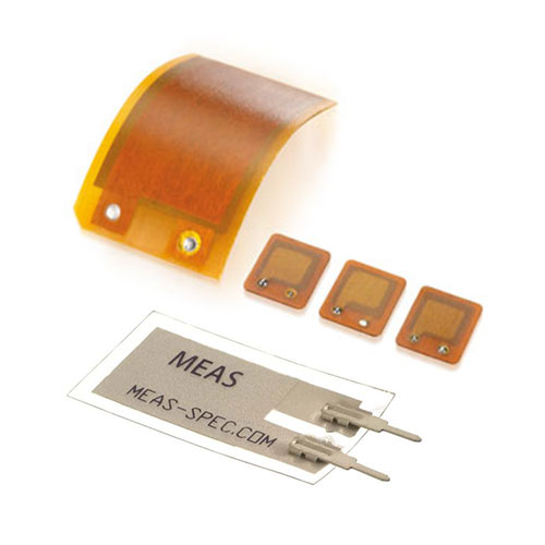 |
|
|
|
|
|
|
|
|
|
|
|
|
|
|
|
|
| Invented in 1880 by Jacques Curie & Pierre Curie. |
| Invented in 1880 by Jacques Curie & Pierre Curie. |
| Invented in 1880 by Jacques Curie & Pierre Curie. |
| Invented in 1880 by Jacques Curie & Pierre Curie. |
| Invented in 1880 by Jacques Curie & Pierre Curie. |
| Generator, Thermoelectric |
| Generator, Thermoelectric |
| Generator, Thermoelectric |
| Generator, Thermoelectric |
| Generator, Thermoelectric |
 |
|
|
|
|
| Definition: Thermoelectric generators, also known as a Seebeck generator, is a device that converts heat directly into electrical energy through a phenomenon known as the Seebeck effect, functioning as heat engines without moving parts. Thermoelectric generators are used in power plants to convert waste heat into electrical power, automobiles to increase fuel efficiency and radioisotopes to generate power for space probes. |
| Definition: Thermoelectric generators, also known as a Seebeck generator, is a device that converts heat directly into electrical energy through a phenomenon known as the Seebeck effect, functioning as heat engines without moving parts. Thermoelectric generators are used in power plants to convert waste heat into electrical power, automobiles to increase fuel efficiency and radioisotopes to generate power for space probes. |
| Definition: Thermoelectric generators, also known as a Seebeck generator, is a device that converts heat directly into electrical energy through a phenomenon known as the Seebeck effect, functioning as heat engines without moving parts. Thermoelectric generators are used in power plants to convert waste heat into electrical power, automobiles to increase fuel efficiency and radioisotopes to generate power for space probes. |
| Definition: Thermoelectric generators, also known as a Seebeck generator, is a device that converts heat directly into electrical energy through a phenomenon known as the Seebeck effect, functioning as heat engines without moving parts. Thermoelectric generators are used in power plants to convert waste heat into electrical power, automobiles to increase fuel efficiency and radioisotopes to generate power for space probes. |
| Definition: Thermoelectric generators, also known as a Seebeck generator, is a device that converts heat directly into electrical energy through a phenomenon known as the Seebeck effect, functioning as heat engines without moving parts. Thermoelectric generators are used in power plants to convert waste heat into electrical power, automobiles to increase fuel efficiency and radioisotopes to generate power for space probes. |
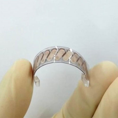 |
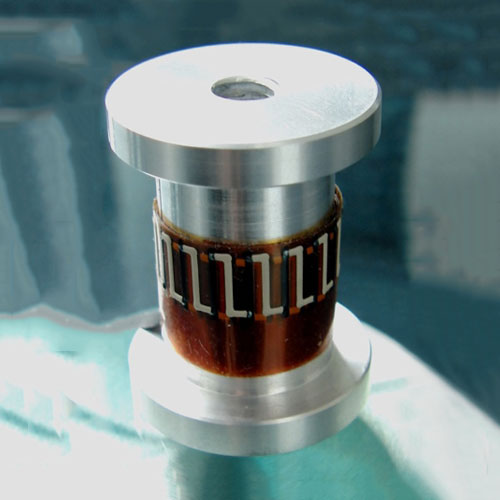 |
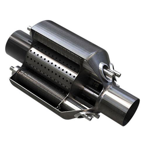 |
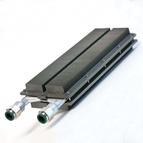 |
|
|
|
|
|
|
|
|
|
|
|
|
|
|
|
|
| Invented in 1821 by Thomas Johann Seebeck. |
| Invented in 1821 by Thomas Johann Seebeck. |
| Invented in 1821 by Thomas Johann Seebeck. |
| Invented in 1821 by Thomas Johann Seebeck. |
| Invented in 1821 by Thomas Johann Seebeck. |
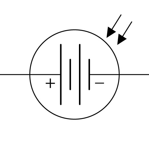 |
|
|
|
|
| Includes: Amorphous Silicon, Cadmium Telluride (CdTe), Copper Indium Gallium Selenide, Crystalline Silicon, Gallium Arsenide Germanium, Monocrystalline, Multi-Junction, Nanocrystal, Organic (OPV), Perovskite, Plasmonic, Plastic, Polycrystalline, Polymer and Quantum Dot Solar Cell Technologies. Definition: As light photons impact into the solar panel, they are absorbed by materials, like silicon, with one layer doped (bonded) with boron and another with phosphorus. These opposing layers lay privy to the prepared chemical bonds to capture the electric charge generated as electrons reach the semiconductor junction. Due to the nature of the cell junction, photodiodes make excellent photon detectors and it was in 1905, that Albert Einstein proposed the then new quantum theory of light, which explained the photoelectric effect which awarded him with his Nobel Prize in Physics. |
| Includes: Amorphous Silicon, Cadmium Telluride (CdTe), Copper Indium Gallium Selenide, Crystalline Silicon, Gallium Arsenide Germanium, Monocrystalline, Multi-Junction, Nanocrystal, Organic (OPV), Perovskite, Plasmonic, Plastic, Polycrystalline, Polymer and Quantum Dot Solar Cell Technologies. Definition: As light photons impact into the solar panel, they are absorbed by materials, like silicon, with one layer doped (bonded) with boron and another with phosphorus. These opposing layers lay privy to the prepared chemical bonds to capture the electric charge generated as electrons reach the semiconductor junction. Due to the nature of the cell junction, photodiodes make excellent photon detectors and it was in 1905, that Albert Einstein proposed the then new quantum theory of light, which explained the photoelectric effect which awarded him with his Nobel Prize in Physics. |
| Includes: Amorphous Silicon, Cadmium Telluride (CdTe), Copper Indium Gallium Selenide, Crystalline Silicon, Gallium Arsenide Germanium, Monocrystalline, Multi-Junction, Nanocrystal, Organic (OPV), Perovskite, Plasmonic, Plastic, Polycrystalline, Polymer and Quantum Dot Solar Cell Technologies. Definition: As light photons impact into the solar panel, they are absorbed by materials, like silicon, with one layer doped (bonded) with boron and another with phosphorus. These opposing layers lay privy to the prepared chemical bonds to capture the electric charge generated as electrons reach the semiconductor junction. Due to the nature of the cell junction, photodiodes make excellent photon detectors and it was in 1905, that Albert Einstein proposed the then new quantum theory of light, which explained the photoelectric effect which awarded him with his Nobel Prize in Physics. |
| Includes: Amorphous Silicon, Cadmium Telluride (CdTe), Copper Indium Gallium Selenide, Crystalline Silicon, Gallium Arsenide Germanium, Monocrystalline, Multi-Junction, Nanocrystal, Organic (OPV), Perovskite, Plasmonic, Plastic, Polycrystalline, Polymer and Quantum Dot Solar Cell Technologies. Definition: As light photons impact into the solar panel, they are absorbed by materials, like silicon, with one layer doped (bonded) with boron and another with phosphorus. These opposing layers lay privy to the prepared chemical bonds to capture the electric charge generated as electrons reach the semiconductor junction. Due to the nature of the cell junction, photodiodes make excellent photon detectors and it was in 1905, that Albert Einstein proposed the then new quantum theory of light, which explained the photoelectric effect which awarded him with his Nobel Prize in Physics. |
| Includes: Amorphous Silicon, Cadmium Telluride (CdTe), Copper Indium Gallium Selenide, Crystalline Silicon, Gallium Arsenide Germanium, Monocrystalline, Multi-Junction, Nanocrystal, Organic (OPV), Perovskite, Plasmonic, Plastic, Polycrystalline, Polymer and Quantum Dot Solar Cell Technologies. Definition: As light photons impact into the solar panel, they are absorbed by materials, like silicon, with one layer doped (bonded) with boron and another with phosphorus. These opposing layers lay privy to the prepared chemical bonds to capture the electric charge generated as electrons reach the semiconductor junction. Due to the nature of the cell junction, photodiodes make excellent photon detectors and it was in 1905, that Albert Einstein proposed the then new quantum theory of light, which explained the photoelectric effect which awarded him with his Nobel Prize in Physics. |
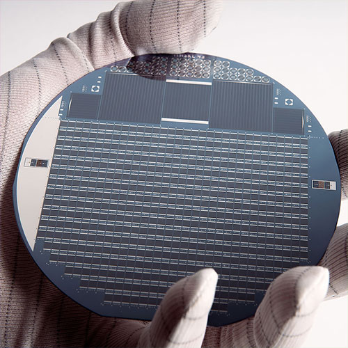 |
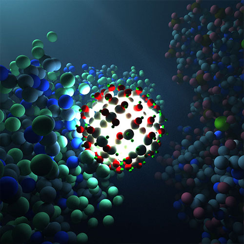 |
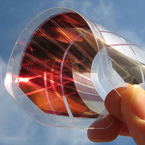 |
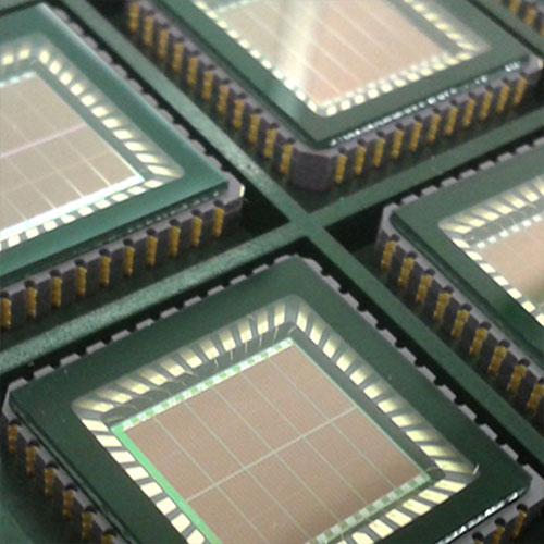 |
|
|
|
|
|
|
|
|
|
|
|
|
|
|
|
|
| Invented in 1839 by Edmond Becquerel. |
| Invented in 1839 by Edmond Becquerel. |
| Invented in 1839 by Edmond Becquerel. |
| Invented in 1839 by Edmond Becquerel. |
| Invented in 1839 by Edmond Becquerel. |
| AUDIO · COMMUNICATION · COMPUTER CONDUCTION · CONTROL · DISPLAY · ILLUMINATION MOTION · POWER · TEMPERATURE · IDENTITY |
| AUDIO · COMMUNICATION · COMPUTER CONDUCTION · CONTROL · DISPLAY · ILLUMINATION MOTION · POWER · TEMPERATURE |
| AUDIO · COMMUNICATION · COMPUTER CONDUCTION · CONTROL · DISPLAY · ILLUMINATION MOTION · POWER · TEMPERATURE |
| AUDIO · COMMUNICATION · COMPUTER CONDUCTION · CONTROL · DISPLAY · ILLUMINATION MOTION · POWER · TEMPERATURE |
| AUDIO · COMMUNICATION · COMPUTER CONDUCTION · CONTROL · DISPLAY · ILLUMINATION MOTION · POWER · TEMPERATURE |
 |
|
|
|
|
| Definition: Heating Elements converts electricity into heat through resistive or Joule heating by passing an electric current through the element, which in turn provides resistance that is the result of heating an element and is independent of the direction of current flow, unlike the Peltier effect which is polarised. Heating elements include Kanthal (FeCrAl) wire, Cupronickel (CuNi) alloy, used for low temperature heating and Nichrome (80% nickel & 20% chromium) which has a high resistance and forms a layer of chromium oxide, when heated for the first time, preventing the material beneath this layer to oxidize. PTC ceramic have a positive thermal coefficient of resistance (Most ceramics have a negative coefficient). Molybdenum disilicide (MoSi2), a silicide of molybdenum, is a refractory ceramic used in heating elements with a melting point of 2030 °C, and is electrically conductive. At high temperatures it forms a passivation layer of silicon dioxide, protecting it from further oxidation. |
| Definition: Heating Elements converts electricity into heat through resistive or Joule heating by passing an electric current through the element, which in turn provides resistance that is the result of heating an element and is independent of the direction of current flow, unlike the Peltier effect which is polarised. Heating elements include Kanthal (FeCrAl) wire, Cupronickel (CuNi) alloy, used for low temperature heating and Nichrome (80% nickel & 20% chromium) which has a high resistance and forms a layer of chromium oxide, when heated for the first time, preventing the material beneath this layer to oxidize. PTC ceramic have a positive thermal coefficient of resistance (Most ceramics have a negative coefficient). Molybdenum disilicide (MoSi2), a silicide of molybdenum, is a refractory ceramic used in heating elements with a melting point of 2030 °C, and is electrically conductive. At high temperatures it forms a passivation layer of silicon dioxide, protecting it from further oxidation. |
| Definition: Heating Elements converts electricity into heat through resistive or Joule heating by passing an electric current through the element, which in turn provides resistance that is the result of heating an element and is independent of the direction of current flow, unlike the Peltier effect which is polarised. Heating elements include Kanthal (FeCrAl) wire, Cupronickel (CuNi) alloy, used for low temperature heating and Nichrome (80% nickel & 20% chromium) which has a high resistance and forms a layer of chromium oxide, when heated for the first time, preventing the material beneath this layer to oxidize. PTC ceramic have a positive thermal coefficient of resistance (Most ceramics have a negative coefficient). Molybdenum disilicide (MoSi2), a silicide of molybdenum, is a refractory ceramic used in heating elements with a melting point of 2030 °C, and is electrically conductive. At high temperatures it forms a passivation layer of silicon dioxide, protecting it from further oxidation. |
| Definition: Heating Elements converts electricity into heat through resistive or Joule heating by passing an electric current through the element, which in turn provides resistance that is the result of heating an element and is independent of the direction of current flow, unlike the Peltier effect which is polarised. Heating elements include Kanthal (FeCrAl) wire, Cupronickel (CuNi) alloy, used for low temperature heating and Nichrome (80% nickel & 20% chromium) which has a high resistance and forms a layer of chromium oxide, when heated for the first time, preventing the material beneath this layer to oxidize. PTC ceramic have a positive thermal coefficient of resistance (Most ceramics have a negative coefficient). Molybdenum disilicide (MoSi2), a silicide of molybdenum, is a refractory ceramic used in heating elements with a melting point of 2030 °C, and is electrically conductive. At high temperatures it forms a passivation layer of silicon dioxide, protecting it from further oxidation. |
| Definition: Heating Elements converts electricity into heat through resistive or Joule heating by passing an electric current through the element, which in turn provides resistance that is the result of heating an element and is independent of the direction of current flow, unlike the Peltier effect which is polarised. Heating elements include Kanthal (FeCrAl) wire, Cupronickel (CuNi) alloy, used for low temperature heating and Nichrome (80% nickel & 20% chromium) which has a high resistance and forms a layer of chromium oxide, when heated for the first time, preventing the material beneath this layer to oxidize. PTC ceramic have a positive thermal coefficient of resistance (Most ceramics have a negative coefficient). Molybdenum disilicide (MoSi2), a silicide of molybdenum, is a refractory ceramic used in heating elements with a melting point of 2030 °C, and is electrically conductive. At high temperatures it forms a passivation layer of silicon dioxide, protecting it from further oxidation. |
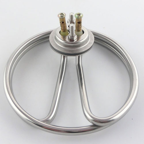 |
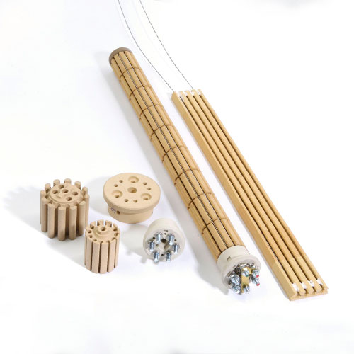 |
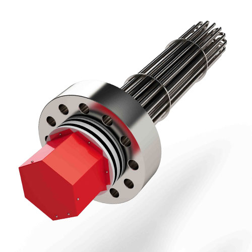 |
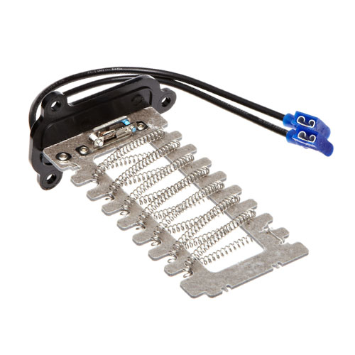 |
|
|
|
|
|
|
|
|
|
|
|
|
|
|
|
|
| Invented in 1840 by James Prescott Joule. |
| Invented in 1840 by James Prescott Joule. |
| Invented in 1840 by James Prescott Joule. |
| Invented in 1840 by James Prescott Joule. |
| Invented in 1840 by James Prescott Joule. |
 |
|
|
|
|
| Definition: The Peltier Element, known also as a peltier device, thermoelectric cooler (TEC) or thermoelectric generator. When used as a cooling or heating element utilising the peltier effect which creates a heat flux between the junction of two dissimilar materials. This solid state cooler or heater transfers heat from one side of the device to the other and will reverse direction when the polarity is inverted. The Peltier Element, can be used as a thermoelectric generator, by utilising the “Seebeck Effect”, which is the direct conversion of heat for electricity at a junction of 2 dissimilar metals. |
| Definition: The Peltier Element, known also as a peltier device, thermoelectric cooler (TEC) or thermoelectric generator. When used as a cooling or heating element utilising the peltier effect which creates a heat flux between the junction of two dissimilar materials. This solid state cooler or heater transfers heat from one side of the device to the other and will reverse direction when the polarity is inverted. The Peltier Element, can be used as a thermoelectric generator, by utilising the “Seebeck Effect”, which is the direct conversion of heat for electricity at a junction of 2 dissimilar metals. |
| Definition: The Peltier Element, known also as a peltier device, thermoelectric cooler (TEC) or thermoelectric generator. When used as a cooling or heating element utilising the peltier effect which creates a heat flux between the junction of two dissimilar materials. This solid state cooler or heater transfers heat from one side of the device to the other and will reverse direction when the polarity is inverted. The Peltier Element, can be used as a thermoelectric generator, by utilising the “Seebeck Effect”, which is the direct conversion of heat for electricity at a junction of 2 dissimilar metals. |
| Definition: The Peltier Element, known also as a peltier device, thermoelectric cooler (TEC) or thermoelectric generator. When used as a cooling or heating element utilising the peltier effect which creates a heat flux between the junction of two dissimilar materials. This solid state cooler or heater transfers heat from one side of the device to the other and will reverse direction when the polarity is inverted. The Peltier Element, can be used as a thermoelectric generator, by utilising the “Seebeck Effect”, which is the direct conversion of heat for electricity at a junction of 2 dissimilar metals. |
| Definition: The Peltier Element, known also as a peltier device, thermoelectric cooler (TEC) or thermoelectric generator. When used as a cooling or heating element utilising the peltier effect which creates a heat flux between the junction of two dissimilar materials. This solid state cooler or heater transfers heat from one side of the device to the other and will reverse direction when the polarity is inverted. The Peltier Element, can be used as a thermoelectric generator, by utilising the “Seebeck Effect”, which is the direct conversion of heat for electricity at a junction of 2 dissimilar metals. |
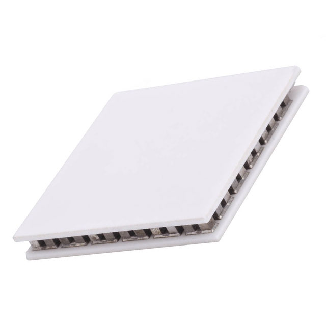 |
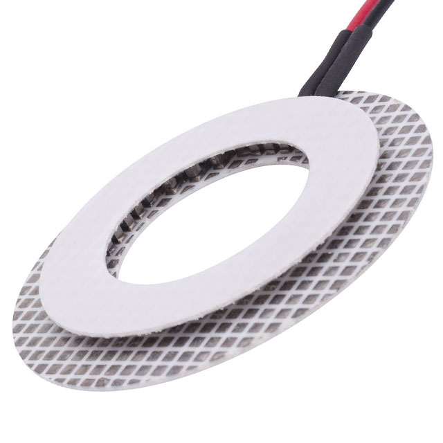 |
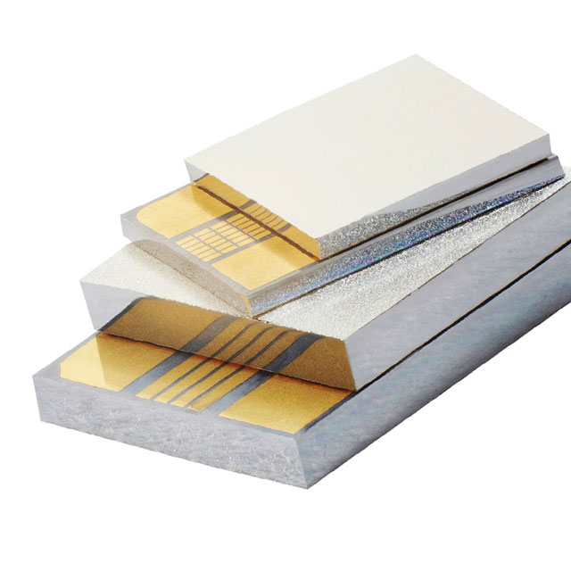 |
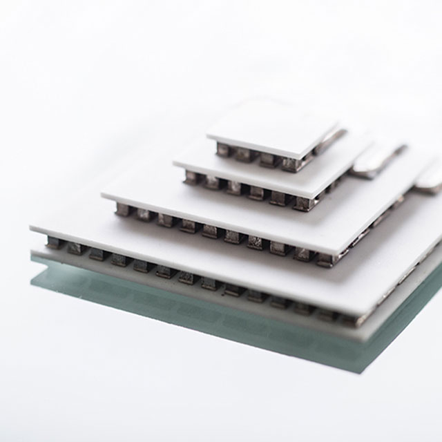 |
|
|
|
|
|
|
|
|
|
|
|
|
|
|
|
|
| Invented in 1834 by Jean Charles Athanase Peltier. |
| Invented in 1834 by Jean Charles Athanase Peltier. |
| Invented in 1834 by Jean Charles Athanase Peltier. |
| Invented in 1834 by Jean Charles Athanase Peltier. |
| Invented in 1834 by Jean Charles Athanase Peltier. |
 |
|
|
|
|
| Definition: For electronic components to maintain a constant nominal operating temperature, this heat exchange device (heatsink) is joined by thermal interface materials (silicon compound or grease) to become an extension of the component by extending the surface area (heatsink fins) to maximise the efficiency of the surrounding cooling medium of air or full immersion. Temperature control at the junction between the component and the heatsink can be controlled by increasing the air velocity, liquid cooling within the heatsink, material choice, protrusion design and surface treatment. Materials used are commonly copper, aluminium alloys or exotic composite materials such as: copper-tungsten pseudo-alloy, silicon carbide in an aluminium matrix, diamond in a copper-silver alloy or beryllium oxide in a beryllium matrix. |
| Definition: For electronic components to maintain a constant nominal operating temperature, this heat exchange device (heatsink) is joined by thermal interface materials (silicon compound or grease) to become an extension of the component by extending the surface area (heatsink fins) to maximise the efficiency of the surrounding cooling medium of air or full immersion. Temperature control at the junction between the component and the heatsink can be controlled by increasing the air velocity, liquid cooling within the heatsink, material choice, protrusion design and surface treatment. Materials used are commonly copper, aluminium alloys or exotic composite materials such as: copper-tungsten pseudo-alloy, silicon carbide in an aluminium matrix, diamond in a copper-silver alloy or beryllium oxide in a beryllium matrix. |
| Definition: For electronic components to maintain a constant nominal operating temperature, this heat exchange device (heatsink) is joined by thermal interface materials (silicon compound or grease) to become an extension of the component by extending the surface area (heatsink fins) to maximise the efficiency of the surrounding cooling medium of air or full immersion. Temperature control at the junction between the component and the heatsink can be controlled by increasing the air velocity, liquid cooling within the heatsink, material choice, protrusion design and surface treatment. Materials used are commonly copper, aluminium alloys or exotic composite materials such as: copper-tungsten pseudo-alloy, silicon carbide in an aluminium matrix, diamond in a copper-silver alloy or beryllium oxide in a beryllium matrix. |
| Definition: For electronic components to maintain a constant nominal operating temperature, this heat exchange device (heatsink) is joined by thermal interface materials (silicon compound or grease) to become an extension of the component by extending the surface area (heatsink fins) to maximise the efficiency of the surrounding cooling medium of air or full immersion. Temperature control at the junction between the component and the heatsink can be controlled by increasing the air velocity, liquid cooling within the heatsink, material choice, protrusion design and surface treatment. Materials used are commonly copper, aluminium alloys or exotic composite materials such as: copper-tungsten pseudo-alloy, silicon carbide in an aluminium matrix, diamond in a copper-silver alloy or beryllium oxide in a beryllium matrix. |
| Definition: For electronic components to maintain a constant nominal operating temperature, this heat exchange device (heatsink) is joined by thermal interface materials (silicon compound or grease) to become an extension of the component by extending the surface area (heatsink fins) to maximise the efficiency of the surrounding cooling medium of air or full immersion. Temperature control at the junction between the component and the heatsink can be controlled by increasing the air velocity, liquid cooling within the heatsink, material choice, protrusion design and surface treatment. Materials used are commonly copper, aluminium alloys or exotic composite materials such as: copper-tungsten pseudo-alloy, silicon carbide in an aluminium matrix, diamond in a copper-silver alloy or beryllium oxide in a beryllium matrix. |
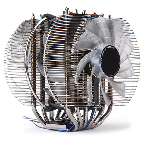 |
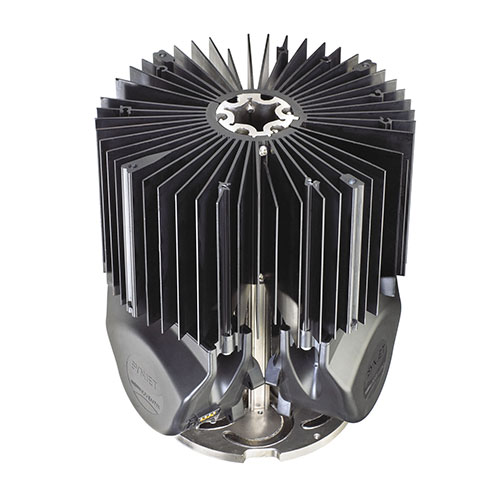 |
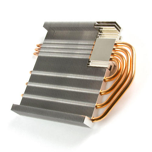 |
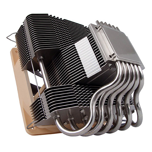 |
|
|
|
|
|
|
|
|
|
|
|
|
|
|
|
|
| Invented in 1956 by Richard Race. |
| Invented in 1956 by Richard Race. |
| Invented in 1956 by Richard Race. |
| Invented in 1956 by Richard Race. |
| Invented in 1956 by Richard Race. |
 |
|
|
|
|
| Definition: A thermoelectric device used to measure temperatures accurately, consist of two dissimilar metals joined so that a potential difference is generated that is representative of the temperature of the junction. There are many composite metals that exhibit these effects and industry have chosen 8 principal types, B, E, J, K, N, R, S & T. This voltage can then be interpreted to calculate the temperature by using the detailed thermocouple reference tables available from this site. |
| Definition: A thermoelectric device used to measure temperatures accurately, consist of two dissimilar metals joined so that a potential difference is generated that is representative of the temperature of the junction. There are many composite metals that exhibit these effects and industry have chosen 8 principal types, B, E, J, K, N, R, S & T. This voltage can then be interpreted to calculate the temperature by using the detailed thermocouple reference tables available from this site. |
| Definition: A thermoelectric device used to measure temperatures accurately, consist of two dissimilar metals joined so that a potential difference is generated that is representative of the temperature of the junction. There are many composite metals that exhibit these effects and industry have chosen 8 principal types, B, E, J, K, N, R, S & T. This voltage can then be interpreted to calculate the temperature by using the detailed thermocouple reference tables available from this site. |
| Definition: A thermoelectric device used to measure temperatures accurately, consist of two dissimilar metals joined so that a potential difference is generated that is representative of the temperature of the junction. There are many composite metals that exhibit these effects and industry have chosen 8 principal types, B, E, J, K, N, R, S & T. This voltage can then be interpreted to calculate the temperature by using the detailed thermocouple reference tables available from this site. |
| Definition: A thermoelectric device used to measure temperatures accurately, consist of two dissimilar metals joined so that a potential difference is generated that is representative of the temperature of the junction. There are many composite metals that exhibit these effects and industry have chosen 8 principal types, B, E, J, K, N, R, S & T. This voltage can then be interpreted to calculate the temperature by using the detailed thermocouple reference tables available from this site. |
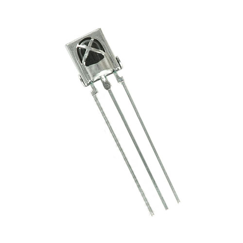 |
 |
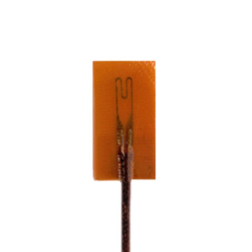 |
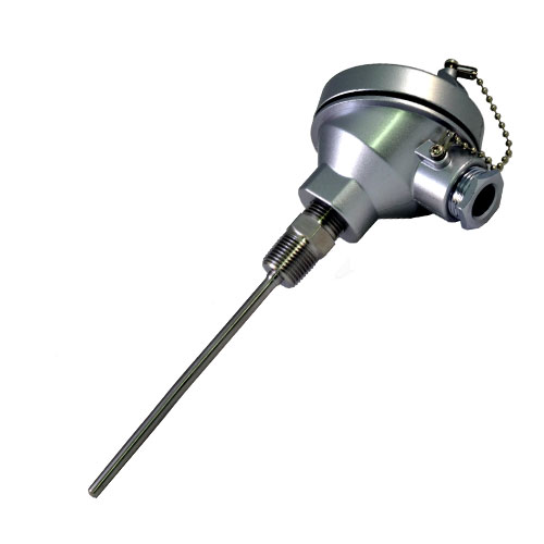 |
|
|
|
|
|
|
|
|
|
|
|
|
|
|
|
|
| Invented in 1821 by Thomas Johann Seebeck. |
| Invented in 1821 by Thomas Johann Seebeck. |
| Invented in 1821 by Thomas Johann Seebeck. |
| Invented in 1821 by Thomas Johann Seebeck. |
| Invented in 1821 by Thomas Johann Seebeck. |
| AUDIO · COMMUNICATION · COMPUTER CONDUCTION · CONTROL · DISPLAY · ILLUMINATION MOTION · POWER · TEMPERATURE · IDENTITY |
| AUDIO · COMMUNICATION · COMPUTER CONDUCTION · CONTROL · DISPLAY · ILLUMINATION MOTION · POWER · TEMPERATURE · IDENTITY |
| AUDIO · COMMUNICATION · COMPUTER CONDUCTION · CONTROL · DISPLAY · ILLUMINATION MOTION · POWER · TEMPERATURE · IDENTITY |
| AUDIO · COMMUNICATION · COMPUTER CONDUCTION · CONTROL · DISPLAY · ILLUMINATION MOTION · POWER · TEMPERATURE · IDENTITY |
| AUDIO · COMMUNICATION · COMPUTER CONDUCTION · CONTROL · DISPLAY · ILLUMINATION MOTION · POWER · TEMPERATURE · IDENTITY |
| EIA 568A & EIA 568B |
| EIA 568A & EIA 568B |
| EIA 568A & EIA 568B |
| EIA 568A & EIA 568B |
| EIA 568A & EIA 568B |
| EIA568A Patch Straight Through |
| EIA568A Patch Straight Through |
| EIA568A Patch Straight Through |
| EIA568A Patch Straight Through |
| EIA568A Patch Straight Through |
| EIA568B Patch Straight Through |
| EIA568B Patch Straight Through |
| EIA568B Patch Straight Through |
| EIA568B Patch Straight Through |
| EIA568B Patch Straight Through |
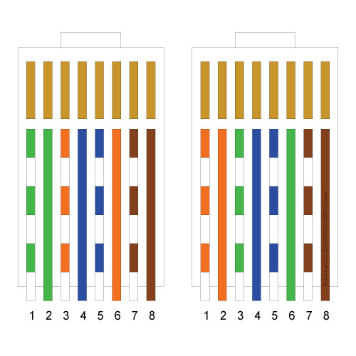
| EIA568A & EIA568B Crossover |
| EIA568A & EIA568B Crossover |
| EIA568A & EIA568B Crossover |
| EIA568A & EIA568B Crossover |
| EIA568A & EIA568B Crossover |
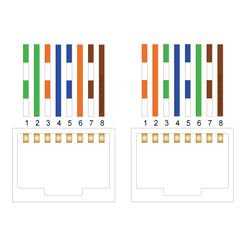
| EIA568A & EIA568B Sockets |
| EIA568A & EIA568B Sockets |
| EIA568A & EIA568B Sockets |
| EIA568A & EIA568B Sockets |
| EIA568A & EIA568B Sockets |
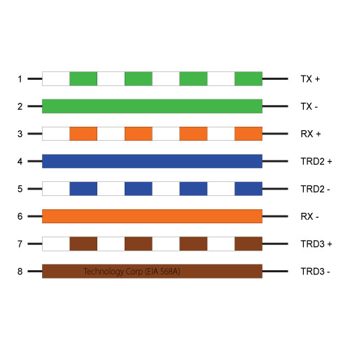
| EIA568A Pinout |
| EIA568A Pinout |
| EIA568A Pinout |
| EIA568A Pinout |
| EIA568A Pinout |
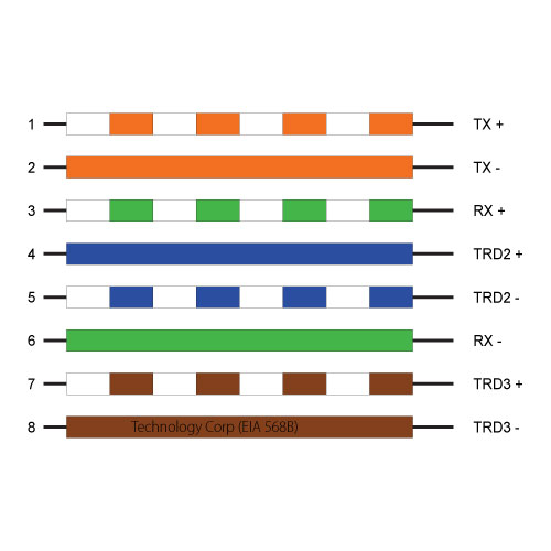
| EIA568B Pinout |
| EIA568B Pinout |
| EIA568B Pinout |
| EIA568B Pinout |
| EIA568B Pinout |