INTELLECTUM VIRTUS
INTELLECTUM VIRTUS
INTELLECTUM VIRTUS
INTELLECTUM VIRTUS
INTELLECTUM VIRTUS
ELECTRICAL ENGINEERING
ELECTRICAL ENGINEERING
ELECTRICAL ENGINEERING
ELECTRICAL ENGINEERING
ELECTRICAL ENGINEERING
TRANSPORTATION
TRANSPORTATION
TRANSPORTATION
TRANSPORTATION
TRANSPORTATION
SCHEMATICS
SCHEMATICS
SCHEMATICS
SCHEMATICS
SCHEMATICS
SCHEMATICS
SCHEMATICS
SCHEMATICS
SCHEMATICS
CONTROLLER, Small Engine
CONTROLLER, Small Engine
CONTROLLER, Small Engine
CONTROLLER, Small Engine
CONTROLLER, Small Engine
In Brief
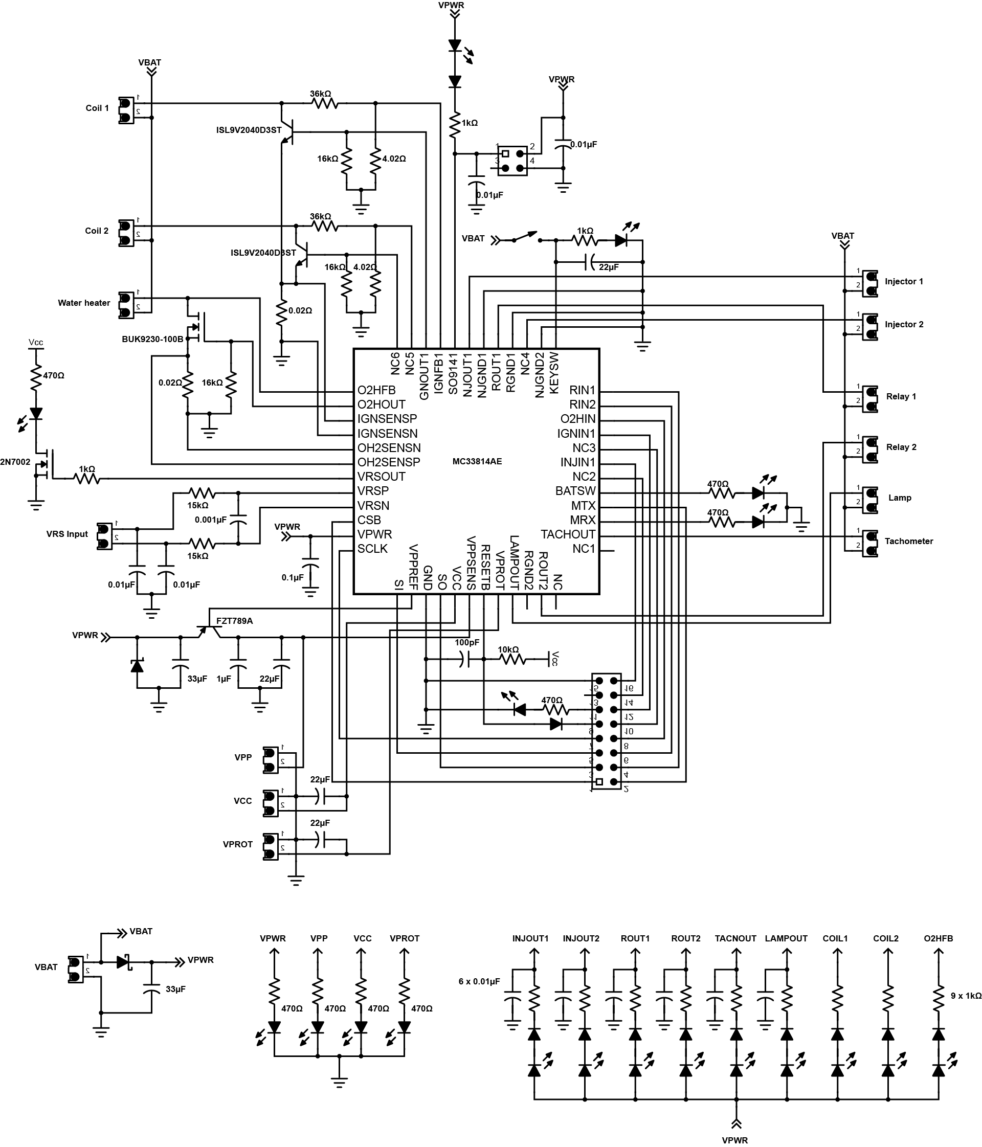
An industrial plant is designed with different control systems in which it varies according to the equipment to be controlled. This design is a general-purpose engine control system, which handles fueled or electrically supplied small engines of industrial plant. It features a 1.0A power relay control, 2.0A relay for fuel pump control, and a lamp driver. The system is also capable of start-up/shut-down control with power sequence logic. It has independent fault protection against surges and possible fluctuations.
In Detail
The design is comprised of a MC33814 engine control analog power IC, a USB to SPI dongle interface, and power conditioning circuitry. It drives the engine electrically or fueled through relays. It also drives the fuel injector that runs the equipment during fueled operation. All 5V VCC power required by the circuit is obtained from the MC33814 built-in power regulator. A 12V VBAT supply provides the power to the three internal voltage regulators. A PC communicates to this project through a USB/SPI dongle (KITUSBSPIDGLEVME) connected to the PC’s USB port. The Freescale SPIGen program provides the user interface to the MC33814 SPI port and allows the user to send commands to the IC and receive status from the IC.
This project is designed to drive several industrial engine functions, a set of screw terminals are designated for control outputs: tachometer output, lamp output, water heater output, two relay outputs, two injector outputs, and two ignition outputs. This kind of control system is very useful in machineries that are usually used in industrial plants for the convenience of the plant operators.
SENSOR, Battery Temperature
SENSOR, Battery Temperature
SENSOR, Battery Temperature
SENSOR, Battery Temperature
SENSOR, Battery Temperature
In Brief
Most of the rechargeable batteries can operate in a wide temperature range, but it doesn’t mean that we can use or charge them at extreme temperatures. Using a battery at high temperature causes it to overheat and makes the cell dry. Charging it at high temperature or even at cold temperature reduces its ability to accept charges. The battery temperature must be brought into moderate level before using or charging it to avoid damages. Using a temperature sensor, battery temperature can be monitored and regulated by controlling the charging current when the battery temperature is at extreme level.
In Detail
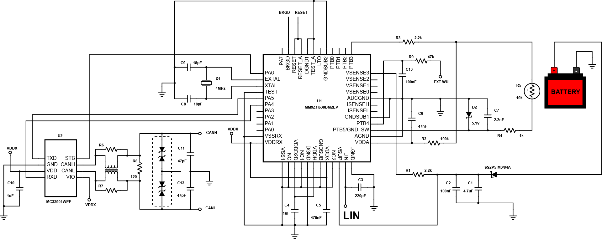
The MM9Z1I638BM2EP Battery Temperature Sensor reference design is an example of a car battery monitoring system that measures not just the voltage or current but also the temperature level of a battery. In this circuit, the MM9Z1I638BM2EP device measures the battery temperature from an external temperature sensor connected to the PTB3 pin. The resistance of the thermistor R5 varies with respect to the change in the temperature of the battery. The changes in the resistance of R5 create a voltage variation across the PTB3 pin of the MM9Z1I638BM2EP device that serves as a temperature level reference of the battery. The temperature data acquired by the device will be stored into the result registers ACQ_ITEMP and ACQ_ETEMP.
The MM9Z1I638BM2EP device interfaces automotive buses through LIN and msCAN interface. The data from the MM9Z1I638BM2EP device are transmitted to the battery charge controller through the two-wire CAN interface to control the charging/discharging rate of the battery. This circuit design is simple yet ideal for microcontroller based temperature sensing application.
SYSTEM, Airbag Chip with PSI5
SYSTEM, Airbag Chip with PSI5
SYSTEM, Airbag Chip with PSI5
SYSTEM, Airbag Chip with PSI5
SYSTEM, Airbag Chip with PSI5
In Brief
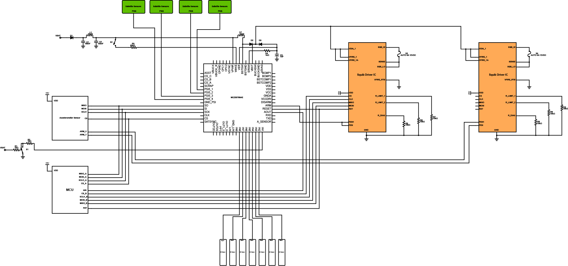
The automotive industries are now into electronics applications in which embedded systems are already part of its major components. In this design, it features the Peripheral Sensor Interface 5 (PSI5), which is the most efficient standard interface of sensors and electronic control units in automotive. It supports complete airbag system that includes system power mode control, supplies for squib firing, satellite sensors, and local Electronic Control Unit (ECU) sensors and ECU logic circuits. It has dedicated safing state machine that complements the airbag’s MCU hardware/software safing approach. The system itself is capable of diagnostics and self-protection.
In Detail
The design is comprised of MCZ33789 Freescale airbag system basis chip that manages the entire airbag partitions and some major components like squib driver IC, SPI communications with MCU, accelerometer sensor, satellite sensors, and dc sensors for monitoring. The squib driver IC supports air bag modules and seat belt retention that functions with accelerometer sensor. The MCU provide the connection of airbag system with the entire electronic applications of the vehicle. The LC filters are provided to ensure frequency range.
The design is used in different airbag system in which it optimizes the capability of providing safety to users. It can be used for further development of safety system in automotive and other vehicle that is prone to crash or collisions. It can help save lives during accidents.
SYSTEM, Vehicle Networking, CAN
SYSTEM, Vehicle Networking, CAN
SYSTEM, Vehicle Networking, CAN
SYSTEM, Vehicle Networking, CAN
SYSTEM, Vehicle Networking, CAN
In Brief
There are some differences that we need to consider when using CAN instead of using LIN. These two protocols should be used together in which this CAN have its own functionality and purpose in automotive in-vehicle networking. In this design, it uses high-speed CAN transceiver that features cost efficient robustness like high system level ESD performance and very high electromagnetic immunity with low electromagnetic emission without common mode choke or other external components. It is also pin and function compatible with market standard especially in automotive.
In Detail
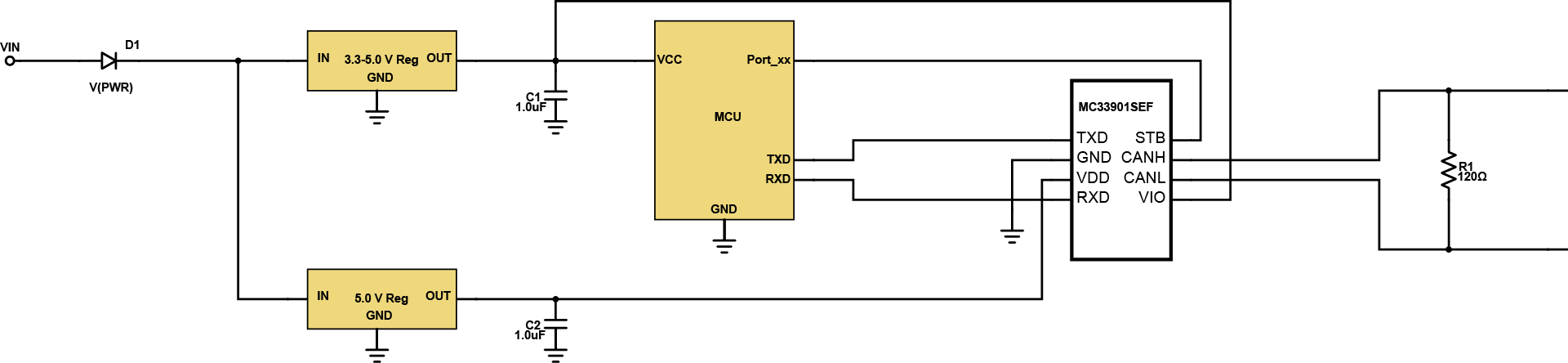
The design is generic in which it is applicable to many CAN applications. In the design, the voltage input or VIN at the left side serves the the primary supply of the system that is connected to a diode as rectifier. The diode specifications will depend on the supply and application. After the rectification, two voltage regulators are provided in which they are responsible of supply the microcontroller or MCU and CAN transceiver with correct voltage rating. The MCU act as the main controller of the system for specified automotive application. It works together with CAN to communicate with the other system in automotive in-vehicle networking.
The use of CAN protocols simplifies a lot of designs whether it is for automotive or industrial. This design is applicable to automotive body systems, transmission, and engine management. It can also be part of industrial applications like factory automation in which CAN protocol is helpful for reducing complexity of the designed system.
TRANSCEIVER, CAN, High Speed
TRANSCEIVER, CAN, High Speed
TRANSCEIVER, CAN, High Speed
TRANSCEIVER, CAN, High Speed
TRANSCEIVER, CAN, High Speed
In Brief
This project is fit for use in automotive and industrial network applications. As a Controller Area Network (CAN) transceiver, this device provides differential transmit capability to the bus and differential receive capability to a CAN controller at signaling rates up to 1Mbps. The device is designed for operation in especially harsh environments and includes many device protection features such as under voltage lockout, over-temperature thermal shutdown, wide common-mode range, and loss of ground protection.
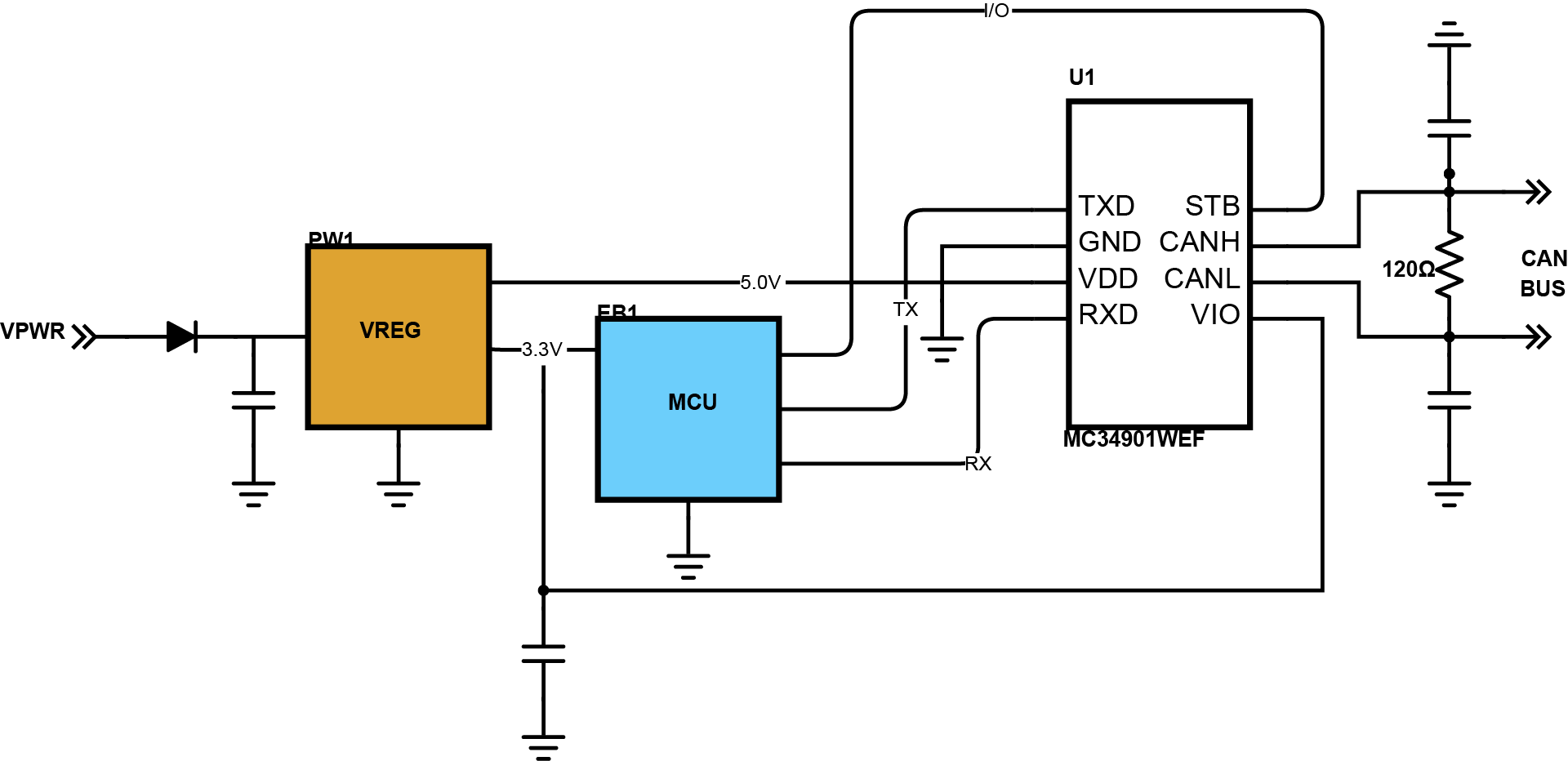
In Detail
The MC34901WEF serves as an interface between a Controller Area Network (CAN) protocol controller and the physical bus and may be used in both 12V and 24V systems. The digital interface level is powered from a VPWR input supply providing true I/O voltage levels for the controller. The transceiver provides differential transmit capability to the bus and differential receive capability to the CAN controller. Due to the wide common-mode voltage range of the receiver inputs, the transceiver is able to reach outstanding levels of Electromagnetic Susceptibility (EMS). Similarly, extremely low Electromagnetic Emission (EME) is achieved by the excellent matching of the output signals.
The MC33901/34901 are SMARTMOS high-speed (up to 1Mbps) CAN transceivers providing the physical interface between the CAN protocol controller of an MCU and the physical dual wires CAN bus. They meet the ISO11898-2 and ISO11898-5 standards, and have low leakage on CAN bus while unpowered. It consumes very low current in standby mode and features automatic adaptation to 3.3 or 5V MCU communication.