INTELLECTUM VIRTUS
INTELLECTUM VIRTUS
INTELLECTUM VIRTUS
INTELLECTUM VIRTUS
INTELLECTUM VIRTUS
ELECTRICAL ENGINEERING
ELECTRICAL ENGINEERING
ELECTRICAL ENGINEERING
ELECTRICAL ENGINEERING
ELECTRICAL ENGINEERING
ROBOTICS
ROBOTICS
ROBOTICS
ROBOTICS
ROBOTICS
SCHEMATICS
SCHEMATICS
SCHEMATICS
SCHEMATICS
SCHEMATICS
SCHEMATICS
SCHEMATICS
SCHEMATICS
SCHEMATICS
CONTROLLER, Motor, H-Bridge
CONTROLLER, Motor, H-Bridge
CONTROLLER, Motor, H-Bridge
CONTROLLER, Motor, H-Bridge
CONTROLLER, Motor, H-Bridge
In Brief
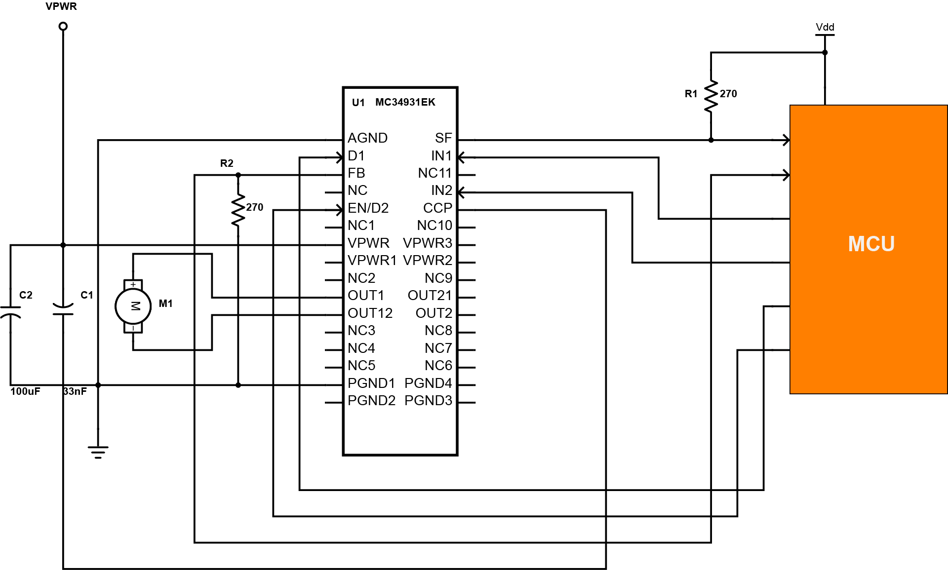
An H bridge is an electronic circuit that allows a voltage to be applied across a load, causing it to reverse the polarity of the motor or to brake the motor. The motor comes to a sudden stop when it brakes, as the motor terminals are shorted. This MC34931EK monolithic H-Bridge Power IC is designed to control any low voltage DC servo motors that are essentially within the voltage and current limits. Exceeding the ratings may cause a malfunction or permanent damage to the device.
In Detail
The 34931 H-Bridge is able to control inductive loads with currents up to 5.0A peak. RMS current capability is subject to the degree of heat sinking provided to the device package. Internal peak current limiting (regulation) is activated at load currents above 6.5A ±1.5A. Output loads can be pulse-width modulated at frequencies up to 20 kHz. A load current feedback feature provides a proportional (0.24% of the load current) current output suitable for monitoring by a microcontroller’s A/D input. A status flag output reports undervoltage, overcurrent, and overtemperature fault conditions. Two independent inputs provide polarity control of two half-bridge totem-pole outputs. The disable inputs are provided to force the H-Bridge outputs to tri-state (high-impedance off-state).
This H-bridge power IC is generally used for DC motor control. It has various applications that can be observed in copiers, printers, factory automation, ATM, vending kiosks, robotics, security camera control, and toll systems.
CONTROLLER, Motor, H-Bridge, 556
CONTROLLER, Motor, H-Bridge, 556
CONTROLLER, Motor, H-Bridge, 556
CONTROLLER, Motor, H-Bridge, 556
CONTROLLER, Motor, H-Bridge, 556
In Brief
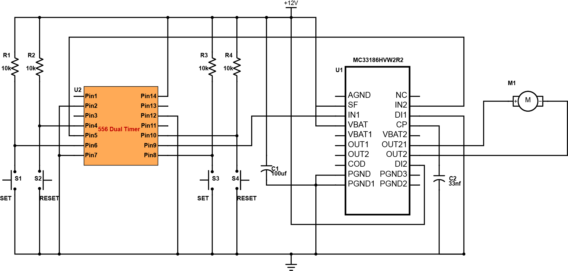
This diagram is the H-bridge motor control with 556 dual timer. In this design, instead of using a microcontroller, it uses a 556 dual timer circuit for controlling the motor, which makes the circuit low cost. The design is only limited to controlling the direction of the motor, whether operate the motor in a forward or reverse direction. The H-bridge used in the circuit is the MC33186HVW2 from Freescale Semiconductor.
In Detail
The schematic diagram consists of three parts: the Input/Control circuit consist of the 556 dual timer circuit, the switching circuit which is the H-bridge MC33186HVW2 chip and the output unit which is the DC motor. The 556 dual timer is configured as two bistable multivibrator. The bistable multivibrator sets the input logic needed in the switching process of the H-bridge. To make the motor turn in a forward direction, S2 must be on RESET to send a logic 0 to IN2 of the MC33186HVW2 and S3 is SET to send a logic 1 to the IN1 of MC33186HVW2. To make the motor turn in reverse direction, S1 must be SET and S4 is on RESET. With this, IN1 is on logic 0 and IN2 is on logic 1.When the inputs are either both high or both low, the motor is set into a free wheeling mode.
This design is applicable to a typical motor control application same with the motor control used in different industries. The system is capable of handling high current applications that makes it more reliable unlike the traditional motor control system. The component is safe to use for commercial and residential purposes since it has short circuit shutdown protections for currents over 8.0A.
CONTROLLER, Motor, Servo, LV-DC
CONTROLLER, Motor, Servo, LV-DC
CONTROLLER, Motor, Servo, LV-DC
CONTROLLER, Motor, Servo, LV-DC
CONTROLLER, Motor, Servo, LV-DC
In Brief
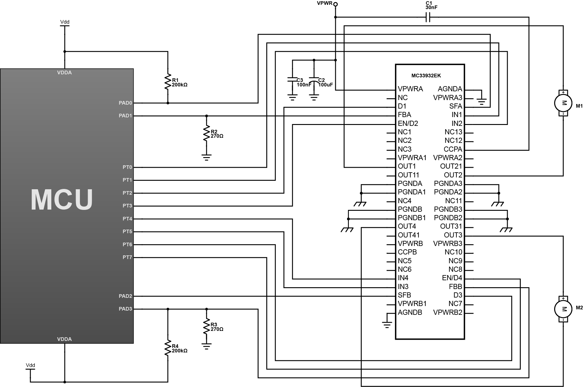
The use of motors to different application is increasing in which majority of the industries are now fully automated using motor control innovation. This design features a typical motor control called H-bridge circuit that enables the motor to have forward and reverse rotation. It can handle transient operation ranging 5V to 40V and able to operate continuously with voltage ranging 8V to 28V. It has two independent monolithic H-Bridge Power ICs in the same package that makes it more compact compared to a typical H-bridge circuit. Each of the H-Bridge MOSFET has 235mO maximum RDS(ON) at 150°C and 3.0 abd 5.0V TTL / CMOS logic compatible inputs. It has also overcurrent regulation and output short-circuit protection. The system is energy efficient that it has < 50uA current draw during its sleep mode.
In Detail
This design is comprised of general components to control motors. The MC33932EK 5.0 A Throttle Control H-Bridge provide the DC load current that put the motor in operation. It has internal charge pump and gate drive circuitry that supports external PWM frequencies up to 11kHz. The FBA and FBB pins are analog feedback output that provides a constant-current source ratioed to the active high side MOSFETs current. The IN1 and IN2 provide the control of the two totem-pole half-bridge outputs. The D1 and EN/D2 are two independent disable inputs that forces the H-bridge outputs to a high-impedance state. The EN/ D2 pin also controls an enable function that allows the IC to be placed in a power-conserving sleep mode. The MCU act as the main controller and provide the ports that can be used to further developed the design. The motors are the output components that relies on the system command.
This is useful to industrial automation and control that it can make the system more efficient due to its body design and numerous operational features. The design can be build easily because it is straightforward that an ordinary hobbyist will be able to understand and make some experiment on it.
MANAGEMENT, Power IC, H-Bridge, Programmable
MANAGEMENT, Power IC, H-Bridge, Programmable
MANAGEMENT, Power IC, H-Bridge, Programmable
MANAGEMENT, Power IC, H-Bridge, Programmable
MANAGEMENT, Power IC, H-Bridge, Programmable
In Brief
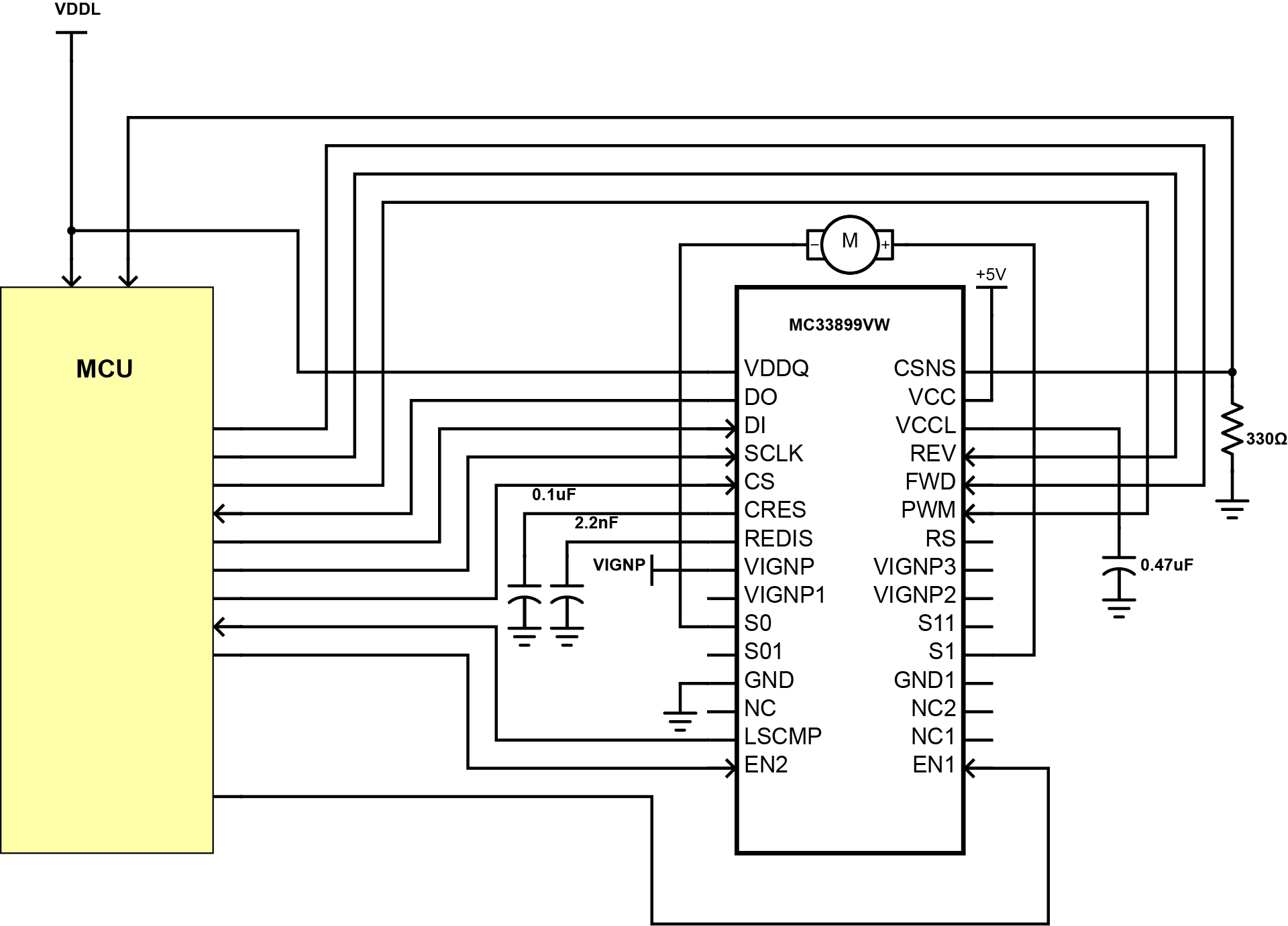
The Freescale’s MC33899VW programmable H-bridge power integrated circuit is designed to drive a DC motor in both forward and reverse rotation under pulse width modulation control. It has synchronous rectification control of the high side MOSFETs and has the ability to control both an SPI-selectable slew rate and current limit that is needed for performance and noise suppression.
In Detail
In the circuit, the VIGNP is the primary power input for the H-Bridge that ranges from 0V to 26.5 V. The S1 and S0 outputs drive the bi-directional DC motor where each output has two internal N-channel MOSFETs connected in a half-bridge configuration between VIGNP and ground. The FWD and REV inputs determine the direction of current flow in the H-Bridge by directing the PWM input to one of the low side MOSFETs. When a change in the current direction is commanded through the microprocessor, the PWM must switch from one low side MOSFET to the other without shoot-through current in the H-Bridge. The REDIS input pin automatically re-enables the low side MOSFET once its input voltage exceeds 4.0V. An external capacitor (CREDIS) determines the time interval while the SCLK input is the clock signal input for synchronization of serial data transfer.
This design has various applications such as throttle control or exhaust gas recirculation actuators. It is particularly well suited for the harsh environment found in automotive powertrain systems. It provides the means to efficiently drive a DC motor in both forward and reverse shaft rotation through a monolithic H-Bridge comprising low RDS(ON) N-channel MOSFETs and integrated control circuitry.