INTELLECTUM VIRTUS
INTELLECTUM VIRTUS
INTELLECTUM VIRTUS
INTELLECTUM VIRTUS
INTELLECTUM VIRTUS
ELECTRICAL ENGINEERING
ELECTRICAL ENGINEERING
ELECTRICAL ENGINEERING
ELECTRICAL ENGINEERING
ELECTRICAL ENGINEERING
POWER
POWER
POWER
POWER
POWER
SCHEMATICS
SCHEMATICS
SCHEMATICS
SCHEMATICS
SCHEMATICS
SCHEMATICS
SCHEMATICS
SCHEMATICS
SCHEMATICS
ADAPTER, Power Over Ethernet
ADAPTER, Power Over Ethernet
ADAPTER, Power Over Ethernet
ADAPTER, Power Over Ethernet
ADAPTER, Power Over Ethernet
In Brief
The Power Over Ethernet (PoE) is a technology used for transmitting power to equipments in a network, using ethernet cables. This PoE is very advantageous, especially when connecting to equipments that are far from power sources. It also offers benefits such as time and cost saving, flexibility, safety, reliability and scalability. Today, the new network equipments are already having built-in PoE features. For non-PoE capable devices, they use the PoE Adapter.
In Detail
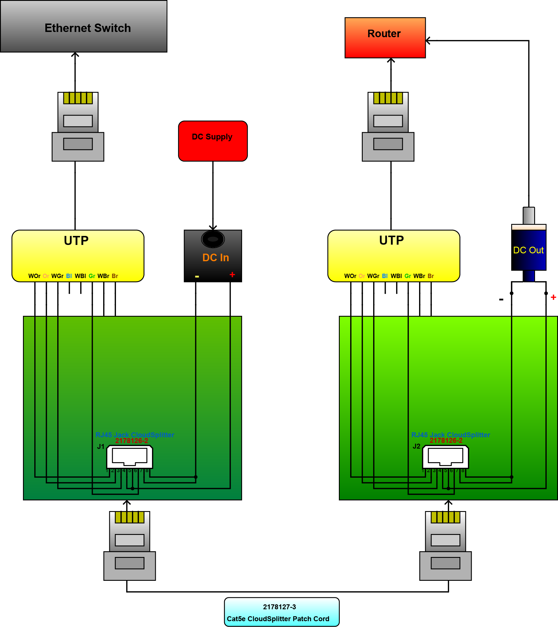
The PoE adapter has two configuration types, the ‘injector’ and the ‘splitter’. The injector collects the data and the power signals, and then injects it into a single ethernet cable. The splitter receives the data and the power from the injector, and then splits the data and power into separate routes. The design features the 2178126-2-jack Cloudsplitter connector from TE Connectivity. It is a single port RJ45 jack and is a surface mount type connector. The connector has 8 positions with a Cat5e performance category.
The diagram shows a non-PoE switch connecting to an isolated router. The injector, which is connected to an external DC supply, plugs into the switch. The data from the switch and the DC power is transmitted into a single ethernet cable by the injector. The splitter then receives the data and power. The splitter separates the data signals from the power signal. The data comes out from the splitter by an ethernet cable going into the router. The power flows through the DC male plug providing power supply to the router. The splitter alone can be used when using a PoE switch, providing power to isolated devices. The PoE adapter applies, but is not limited to IP Cameras, IP Phones and wireless access points.
CONVERTER, DC-to-DC 1.5A
CONVERTER, DC-to-DC 1.5A
CONVERTER, DC-to-DC 1.5A
CONVERTER, DC-to-DC 1.5A
CONVERTER, DC-to-DC 1.5A
In Brief
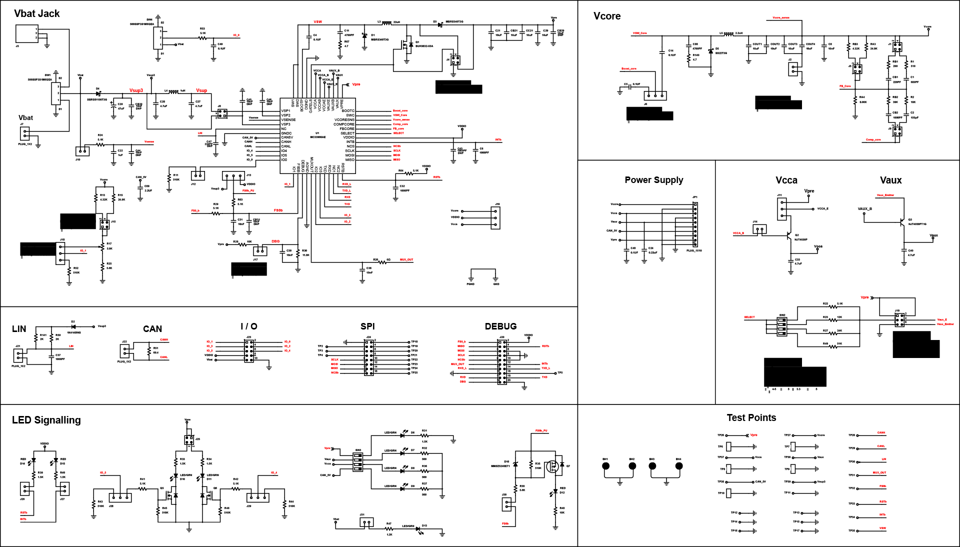
The design of the circuit is a DC to DC converter. It supports up to 1.5A on VCORE. It features a DC/DC converter that provides power to MCUs. It also deals with the optimization of energy consumption by using DC/DC linear regulators and ultra-low-power saving modes. The model contains a Serial Peripheral Interface (SPI), an advanced functional safety measure that allows control and diagnostics with the MCUs.
In Detail
The KIT33907AEEVB and KIT33908AEEVB evaluation boards demonstrate the functionality of the SMARTMOS MC33907 and MC33908 power system basis chips, respectively. These ICs are equipped with an intelligent power management system including safety features targeting the latest ISO26262 automotive functional safety standard. The evaluation board is a standalone board that can be used either with a compatible microcontroller or with PC. In the latter case, it is necessary to use a KITUSBSPIDGLEVME accessory interface board. The MC33907 and the MC33908 are multi-output ICs with power supply and HSCAN transceiver. These devices have been designed specifically for automotive market. All features of thse two ICs are the same except that the MC33907 is designed to support up 800 mA on VCORE, while MC33908 will support up to 1.5A on VCORE.
The DC to DC converter that supports up to 1.5A on VCORE has the following applications: electrical power steering, engine management, battery management, active suspension, gearbox, transmission, electrical vehicle (EV), hybrid electrical vehicle (HEV) and advanced driver assistance systems.
MANAGEMENT, 4-Cell Lithium Battery
MANAGEMENT, 4-Cell Lithium Battery
MANAGEMENT, 4-Cell Lithium Battery
MANAGEMENT, 4-Cell Lithium Battery
MANAGEMENT, 4-Cell Lithium Battery
In Brief
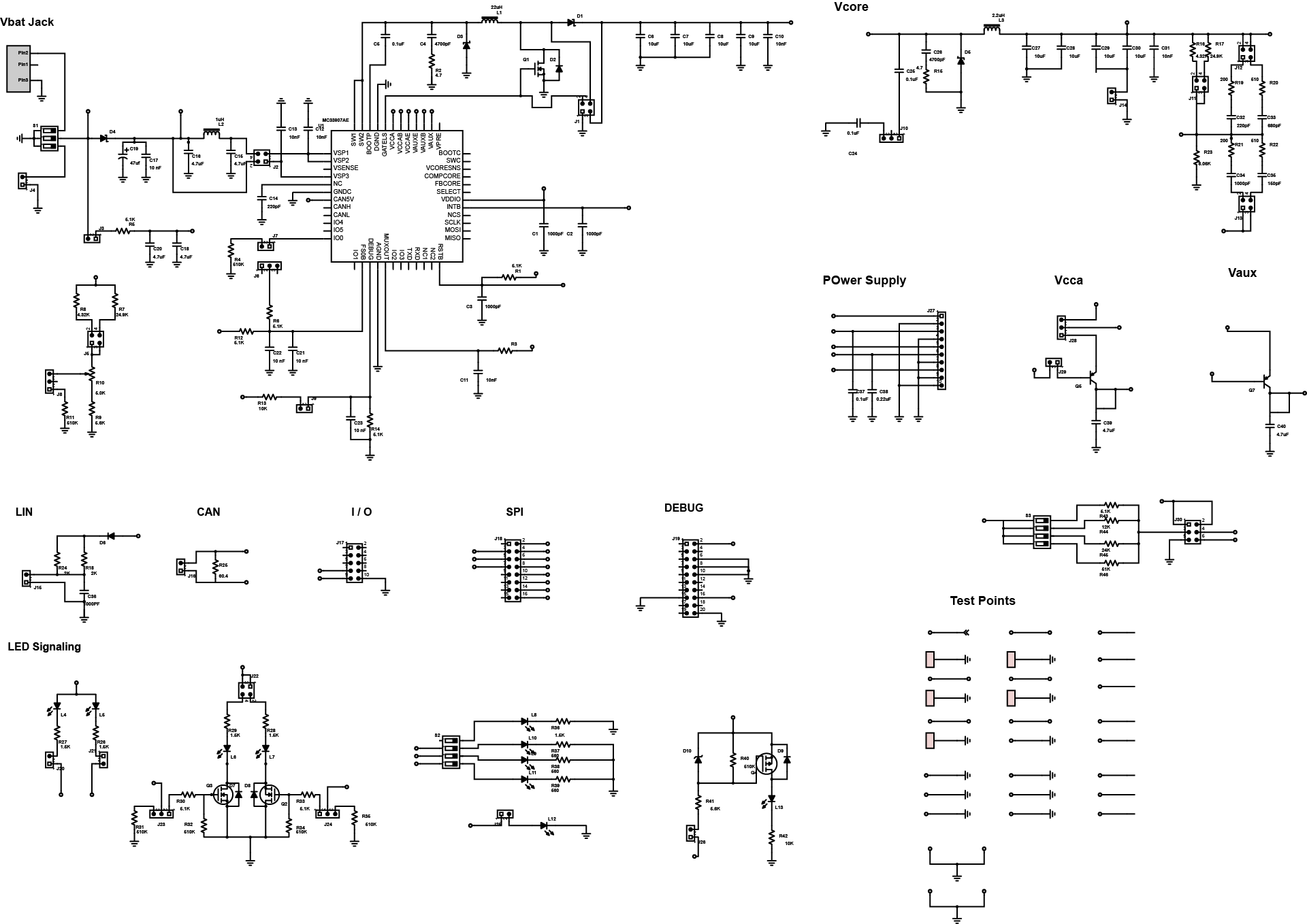
This design is a battery management circuit, which involves the use of CAN/LIN interface. The system addresses the matter about managing rechargeable batteries. This design features an 8-output hardware configurable, high side/low switch with 16-bit serial input control using the serial peripheral interface (SPI). Two of the outputs are directly controlled using microcontrollers which are applicable in pulse-width modulation. The design also features high-speed CAN interface that is used to convert digital protocol information into an analog CAN communication.
In Detail
The RD9Z1-638-4Li reference design is a Battery Management System (BMS) for 4-Cell Li-Ion battery applications featuring the MM9Z1_638 Battery Sensor Module. The RD9Z1-638-4Li is built to demonstrate the product capabilities in a 4-cell Li-Ion application where high EMC performance is required to obtain high accuracy measurements on key battery parameters. The board features an 8-pin standalone CAN transceiver to interface with other modules. Very high EMC robustness and performances are achieved by the Freescale MC33901 CAN High-Speed Transceiver. For cell balancing function and general purpose switches, the board features the Freescale MC33879 Configurable Octal Serial Switch.
The design is useful to automotive applications such as engine management, climate controls, communication, and safety systems. The circuit’s function is suitable for a hybrid electric vehicle which monitors the condition of individual cells, make up the battery and maintains all the cells within the operating limits. It also provides information on the State of Charge (SOC) and State of Health (SOH) of the battery.
SOLAR, Signal Control
SOLAR, Signal Control
SOLAR, Signal Control
SOLAR, Signal Control
SOLAR, Signal Control
In Brief
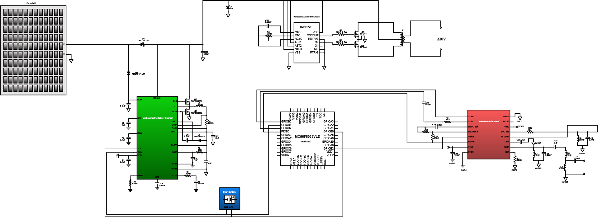
This simple design features a solar energy charging and powering system in which analog signals are converted to digital for more efficient control over the system. It has compact component that integrates with the functionality of a microcontroller and a very efficient digital signal controller. It has flexible set of peripherals with low cost solution suited for different applications. The storage part is able to withstand over 2A charge current with 6-bit charge current resolution. The voltage has charge accuracy of +/- 0.6% and 11-bit charge voltage resolution.
In Detail
The design is comprised of MC56F8035VLD digital signal controller that interfaces power line IC to a charging IC. It monitors the charging status as well as the flow of direct AC supply with the use of inverters. The multichemistry battery charging IC provides the charging capability of the system while the energy generated by the solar panel is not in use. It charges a smart battery that has built-in Battery Management System (BMS). The powerline interface IC or power line data access arrangement IC provides the real-time metering and monitoring of the system. It is built with external LC filter that ensures the accuracy of the energy monitoring.
The design is applicable to low voltage and high voltage power management system like the different types of solar energy system. It is useful to Switched-Mode Power Supply (SMPS), portable equipment with rechargeable batteries, handset car kits, and some of the consumer electronics devices. It is also useful to the development of efficient energy management with optimum solutions.
WIRELESS, Power Receiver
WIRELESS, Power Receiver
WIRELESS, Power Receiver
WIRELESS, Power Receiver
WIRELESS, Power Receiver
In Brief
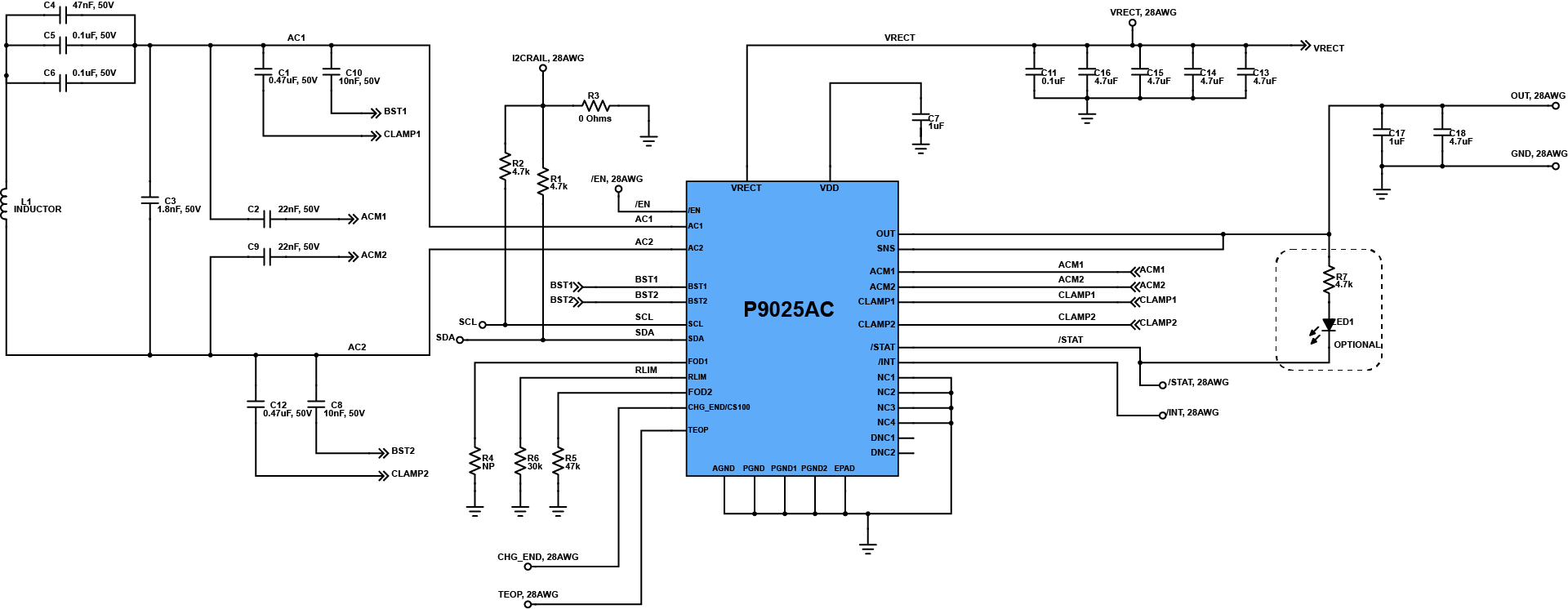
The technological development of power transmission evolves to integrated circuits in which it optimizes the capability of wireless power transfer. This latest design of IDT on wireless application featured a wireless power receiver board with fully integrated single chip solution that requires only few external discrete components . It can support up to 6W output power and WPC V1.1.2 compliant. It has peak efficiency of up to 83%. It make use of an integrated synchronous full bridge rectifier and integrated tracking LDO output stage for its regulation. The system has its own protection against over temperature/current/voltage while a thermal control loop is used to manage the temperature of the system.
In Detail
The design is comprised of P9025AC wireless power receiver IC in which it act as the main component of the wireless charging application. It drives a coil that helps to interact with the transmitter board. It uses capacitors to improve noise immunity and overall performance. The resistors are used as pull ups for I2C interface pins. The AC1-2 pins are used for the inputs that is received by the system while the ACM1-2 are used for AC modulation input.. The SDA and SCL are for I2C interface while the other pins are used for its monitoring or detection.
There are already common applications of wireless charging such as wearable devices and hand-held GPS, but still it continue to evolve that it can now be used by tablets, DSC, DVC, cellular phones, and other types of handheld products. It provides convenience to people and productivity improvements to industries.
WIRELESS, Power Transmitter
WIRELESS, Power Transmitter
WIRELESS, Power Transmitter
WIRELESS, Power Transmitter
WIRELESS, Power Transmitter
In Brief
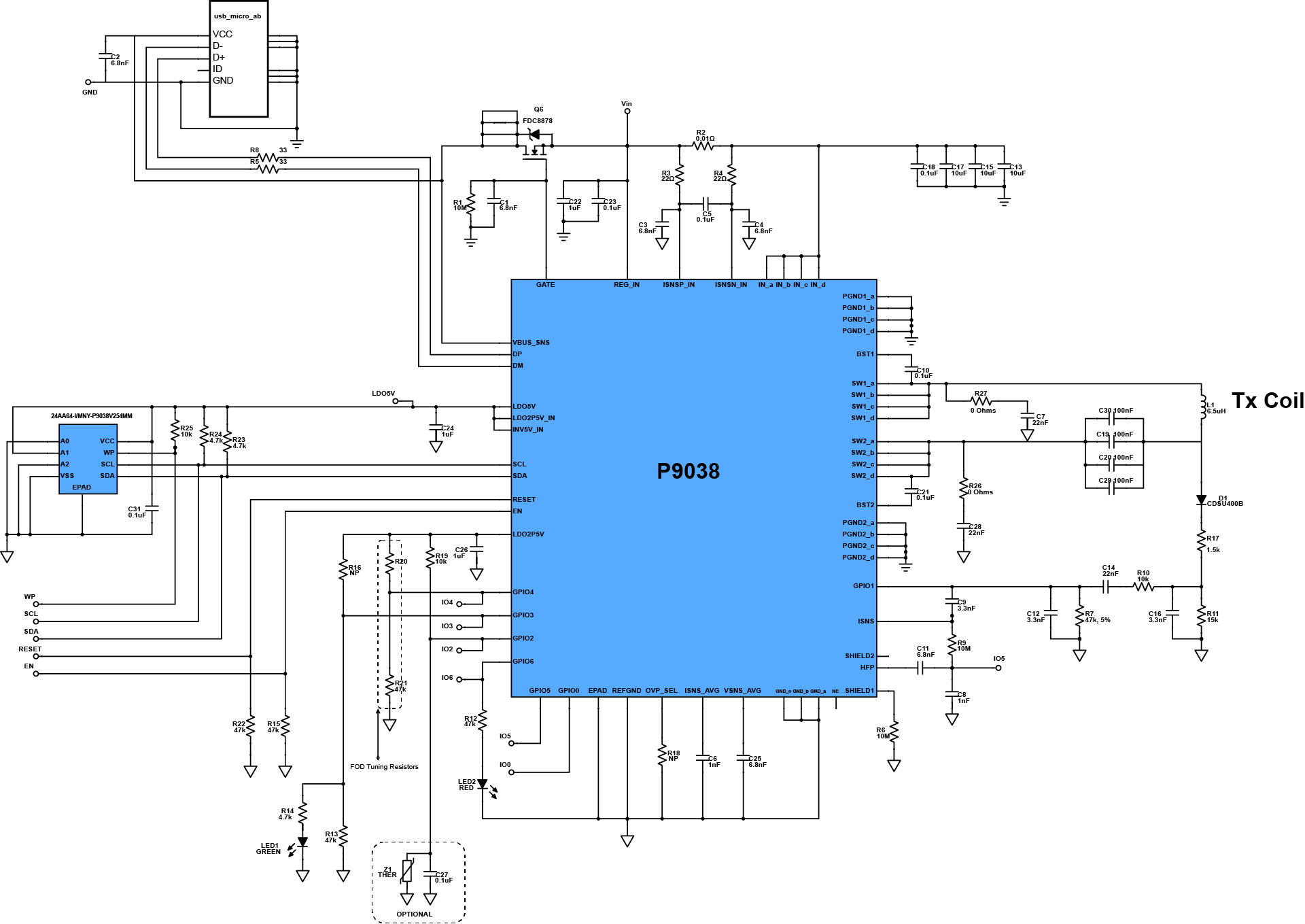
This design features a wireless power transmitter that supports Qi enabled smartphones and other devices. It operates from a 4.5 – 6.9V input and supports up to 8W power transfer at approximately 1.6A. The low cost adaptors and other unregulated adaptors or supplies help prevent surges. Because, it is a fully integrated design, BOM cost is minimal while still offering highly efficient operations with very low RDS(ON). It also has programmable input in-rush control that can be used to add up protections and configurations of the system.
In Detail
The design’s main component is comprised of a P9038-RNDG single-chip WPC 1.1 5V wireless power transmitter IC. It drives the coil for induction with capacitor filters and supports load changes. A serial EEPROM is provided to store configurations of the system that is accessible through I2C communication. The micro USB type AB port can be used for power and serial communication. The N-channel PowerTrench MOSFET is used for switching and it is supported by the RC circuit which ensures gate supplies. The inductor coil used for wireless power charging transmission is connected to a switching diode attached to ISNS pin, providing sensing of the inductor current. A thermistor is connected to the GPIO2 to prevent overheating, while LEDs provide indication.
This design is applicable to charging mats or pads that are now available in the market. It can be interfaced to office furniture, public facilities, and personal computer docks to optimize wireless power transfer and is ideal for a variety of wireless charging applications such as cellphones and other portable electronic devices.