INTELLECTUM VIRTUS
INTELLECTUM VIRTUS
INTELLECTUM VIRTUS
INTELLECTUM VIRTUS
INTELLECTUM VIRTUS
ELECTRICAL ENGINEERING
ELECTRICAL ENGINEERING
ELECTRICAL ENGINEERING
ELECTRICAL ENGINEERING
ELECTRICAL ENGINEERING
MEASUREMENT
MEASUREMENT
MEASUREMENT
MEASUREMENT
MEASUREMENT
SCHEMATICS
SCHEMATICS
SCHEMATICS
SCHEMATICS
SCHEMATICS
SCHEMATICS
SCHEMATICS
SCHEMATICS
SCHEMATICS
ACCELEROMETER, 3 Axis with ATMEGA16
ACCELEROMETER, 3 Axis with ATMEGA16
ACCELEROMETER, 3 Axis with ATMEGA16
ACCELEROMETER, 3 Axis with ATMEGA16
ACCELEROMETER, 3 Axis with ATMEGA16
In Brief
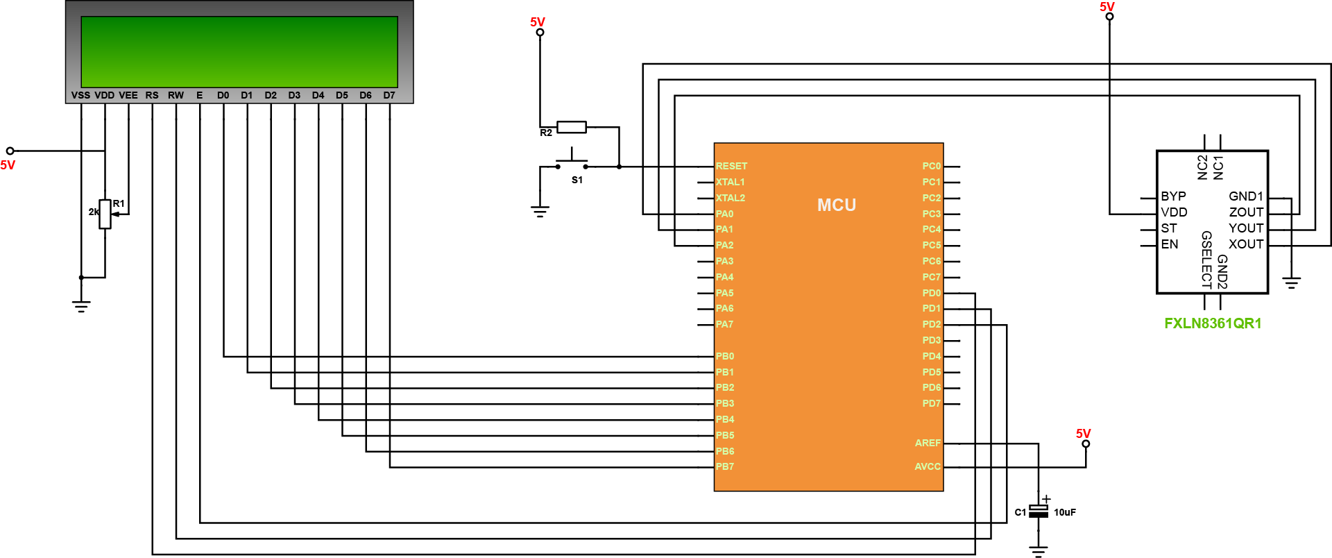
This project addressed the matter on how to interface an accelerometer sensor to a microcontroller. The accelerometer used is a FXLN8361QR1, a 3-axis, low-power, low-g, analog output accelerometers that consist of an acceleration sensor. The analog outputs for the X, Y, and Z axes are internally compensated for zero-g offset and sensitivity, and then buffered to the output pads. The outputs have a fixed zero-g offset of 0.75V, irrespective of the VDD supply voltage. The bandwidth of the output signal for each axis may be independently adjusted using external capacitors.
In Detail
In this project, the interfacing of a 3-axis accelerometer sensor FXLN8361 with AVR ATmega16 microcontroller is essentially discussed. Here, we will measure the tilt of the accelerometer sensor or the material to which the accelerometer sensor is attached and we will display the three outputs of accelerometer sensor in a 16X2 alphanumeric LCD. But, the three outputs of 3-axis accelerometer sensor are analog in nature and microcontroller cannot process the analog signal directly. So, first it will convert the three analog outputs of ADXL335 accelerometer sensor to digital values using its analog to digital converter and then it will display the three converted digital values in the 16X2 alphanumeric LCD. Now, we will tilt the accelerometer sensor or the material to which the sensor is attached in different direction and we will see the changes in its output values in the 16×2 alphanumeric LCD.
This accelerometer measures static acceleration of gravity in tilt-sensing application, as well as dynamic acceleration resulting from motion, shock, or vibration. The accelerometer sensor is used in mobile devices, gaming systems, disk drive protection, image stabilization, sports devices, health devices and etc.
BAROMETER, MPL115A2
BAROMETER, MPL115A2
BAROMETER, MPL115A2
BAROMETER, MPL115A2
BAROMETER, MPL115A2
In Brief
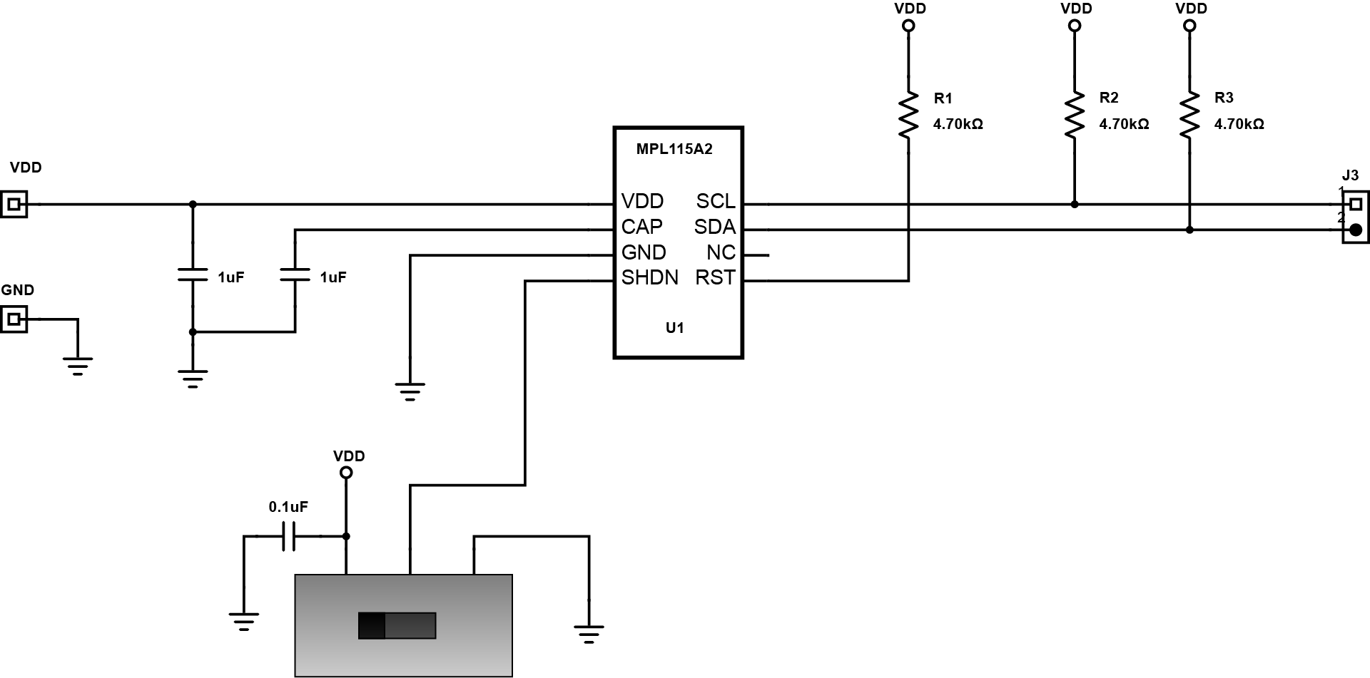
Digital barometer is a scientific instrument that measures atmospheric pressure. It effectively measures subtle pressure changes caused by weather such as this evaluation board that specifically uses the Freescale’s MPL115A which digital I2C output targeting low cost commercial applications. The device employs a MEMS PRT pressure sensor with a conditioning IC to provide accurate pressure data. The sensor output is accurate to ±1 kPa over the 50 kPa to 115 kPa pressure range. An integrated ADC provides digitized temperature and pressure sensor outputs via an I2C or SPI bus.
In Detail
The evaluation board is comprised with sensor parts, pull-up resistors and decoupling capacitors that is soldered onboard. Calibration data is housed in on-board ROM. This data is used typically by a host microcontroller to apply a compensation algorithm to the raw ADC data from the pressure sensor and may be accessed at any time. The Calibration data is stored as a series of coefficients that are applied to the raw data to compensate for temperature and pressure variation in the raw output. The MPL115A interfaces to a host (or system) microcontroller in the user’s application where all communications are via I2C. During initial power-up, all circuit elements are active and I2C port pins are high impedance and associated registers are cleared. The user then typically accesses the part and reads the coefficient data. The main circuits within the slave device are disabled during read activity. The coefficients are usually stored in the host microcontroller local memory but can be re-read at any time. Data conversion is the first step that is performed each time a new pressure reading is required which is initiated by the host sending the CONVERT command. The main system circuits are activated (wake) in response to the command and after the conversion completes, the result is placed into the Pressure and Temperature ADC output registers. After the conversion has been given sufficient time to complete, the host microcontroller reads the result from the ADC output registers and calculates the compensated pressure, a barometric/atmospheric pressure value which is compensated for changes in temperature and pressure sensor linearity. From this step the host controller may either wait and then return to the Data Conversion step to obtain the next pressure reading or it may go to the Shutdown step.
The MPL115A is an absolute pressure sensor with digital output for low cost applications. A miniature 5 x 3 x 1.2 mm LGA package ideally suits it for portable electronics and space constrained applications. With its wide operating temperature range from -40°C to +105°C definitely fits demanding environmental requirements. Digital barometer has various applications for use in weather stations, air control systems, industrial equipment and health monitoring.
MOTION, Intelligent Sensing Platform
MOTION, Intelligent Sensing Platform
MOTION, Intelligent Sensing Platform
MOTION, Intelligent Sensing Platform
MOTION, Intelligent Sensing Platform
In Brief
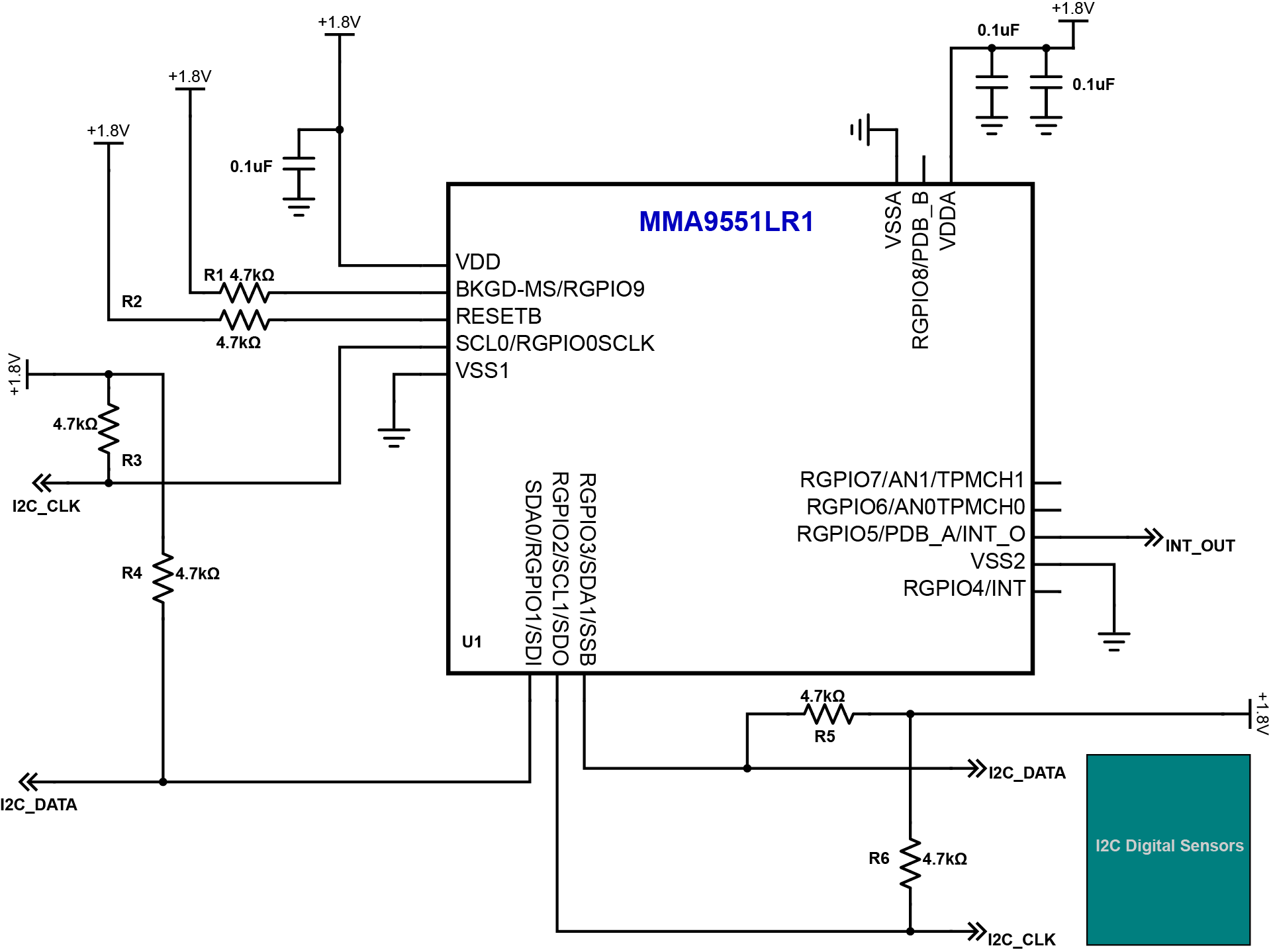
The MMA955xL platform as a sensor hub is an intelligent sensing hub with built-in accelerometer, signal conditioning, and data conversion with 32-bit programmable microcontroller and temperature sensor. In addition, it has a second I2C bus and one external analog input, which can be monitored using the on-chip Analog-to-Digital (ADC). This unique blend transforms Freescale’s MMA955xL into an intelligent, high precision, motion-sensing platform able to manage multiple sensor inputs.
In Detail
The combination of low power consumption and powerful features means that the MMA955xL platform can effectively operate as a power controller for handheld units such as industrial scanners, Personal Digital Assistant (PDA), and games. The host platform can put itself to sleep with confidence that the MMA955xL device will issue a wake request should any external event require its attention. The MMA955xL device is programmed and configured with the codewarrior development studio for microcontrollers software. This standard integrated design environment enables customers to quickly implement custom algorithms and features to exactly match their application needs. Using the master I2C port, the MMA955xL device can manage secondary sensors, such as pressure sensors, magnetometers, or gyroscopes. This allows sensor initialization, calibration, data compensation, and computation functions to be off-loaded from the system application processor. The MMA955xL device also acts as an intelligent sensing hub and a highly configurable decision engine. Total system power consumption is significantly reduced because the application processor stays powered down until absolutely needed.
This device is optimized for use in portable and mobile consumer products that can make system-level decisions required for practical applications such as gesture recognition, pedometer functionality, tilt compensation and calibration, and activity monitoring. This may be applicable to tablets, digital cameras, smartbooks, laptops, gaming and security system as well as used in medical applications.
TEMPERATURE, Sensing with Raspberry Pi
TEMPERATURE, Sensing with Raspberry Pi
TEMPERATURE, Sensing with Raspberry Pi
TEMPERATURE, Sensing with Raspberry Pi
TEMPERATURE, Sensing with Raspberry Pi
In Brief
Temperature sensing equipment is a very useful device for industries like HVAC, medical equipment, automotive, food processing, chemical handling and safety applications. Temperature sensors are used to measure heat in processes to ensure that the operation is in a safe range.
In Detail
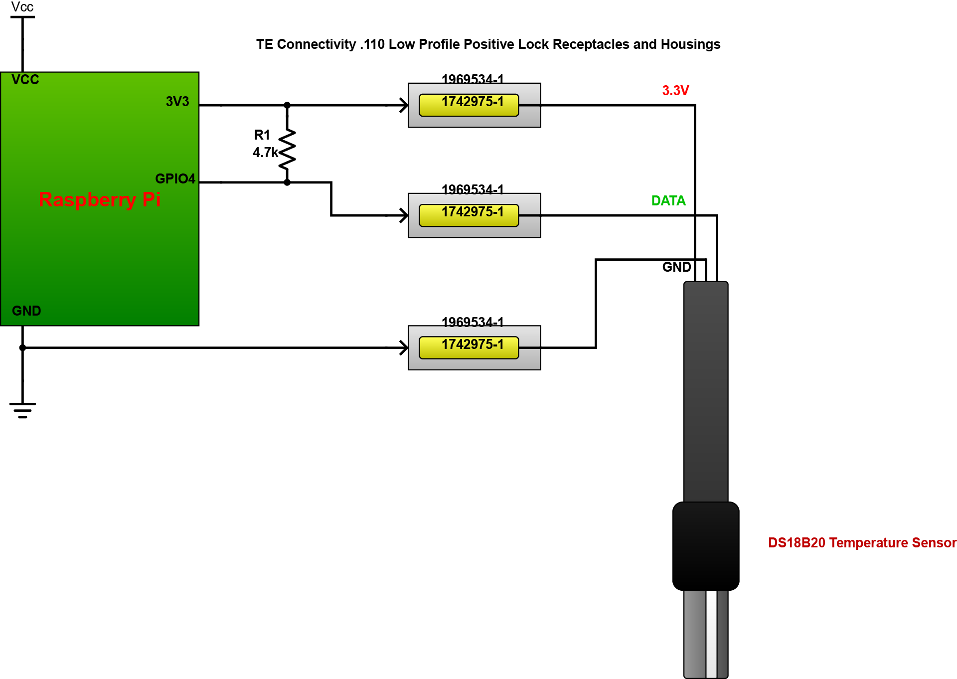
In the design, the circuit uses a digital temperature sensor, specifically, the DS18B20. It is a high temperature with waterproof features. With this sensor, it becomes convenient to measure heat from places that are difficult. With a waterproof system, the sensor can also be deployed in wet areas and has a usable temperature range up to 125° C. It has 9 to 12 selectable resolutions and operates on a One Wire interface. The circuit also involves a data control/processing unit, which in this case is a Raspberry Pi. The Raspberry Pi includes support to DS18B20 sensors, which makes them compatible components. The design also features the .110 Low Profile Positive Lock connectors from TE Connectivity, which helps on contact retention between the sensors and the circuit. The connector reduces mating force and enhances safety and reliability of the mated pair with positive lock design. It also improves ease of assembly with low profile ergonomic housing design and reduced insertion force.
The Raspberry Pi has no ADC, however, the sensor has its own ADC that converts analog into digital signals. The data travels from the sensor to an IO pin in the raspberry pi for processing. The pull-up resistor in the circuit provides the stability and reliability of data transfer. The output of the circuit is fairly precise with ±0.5°C Accuracy from -10°C to +85°C. The circuit can be operated with a power source of 3.0V to 5.5V.The circuit can be modified through adding more sensors in which add more functionality in the system. Additional DS18B20 sensors can also be added in parallel using only a single pull-up resistor.