INTELLECTUM VIRTUS
INTELLECTUM VIRTUS
INTELLECTUM VIRTUS
INTELLECTUM VIRTUS
INTELLECTUM VIRTUS
ELECTRICAL ENGINEERING
ELECTRICAL ENGINEERING
ELECTRICAL ENGINEERING
ELECTRICAL ENGINEERING
ELECTRICAL ENGINEERING
CONTROL
CONTROL
CONTROL
CONTROL
CONTROL
SCHEMATICS
SCHEMATICS
SCHEMATICS
SCHEMATICS
SCHEMATICS
SCHEMATICS
SCHEMATICS
SCHEMATICS
SCHEMATICS
INTERFACE, IO Management with CAN
INTERFACE, IO Management with CAN
INTERFACE, IO Management with CAN
INTERFACE, IO Management with CAN
INTERFACE, IO Management with CAN
In Brief
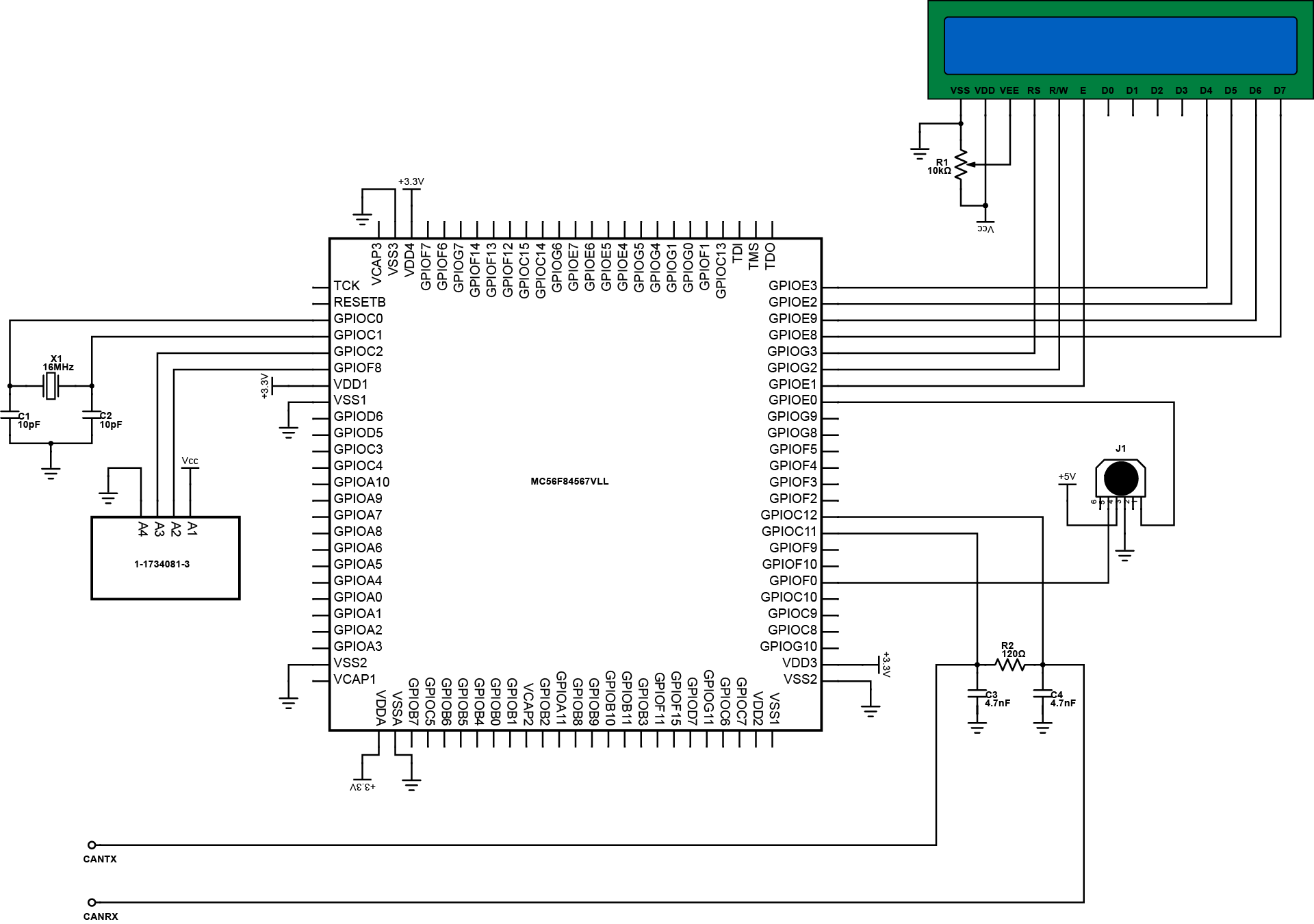
In the midst of automotive and industrial demand in the market, embedded electronic systems also increase in which the developments of some industries are now using this technology. This design features a system basis chip that can operate as LIN and CAN. It uses a DSC chip that combines the functionality of an MCU and a processing power of a DSP. It has 288KB on-chip memory and 32KB RAM and it can operate up to 80MHz program execution from both internal flash memory and RAM.
In Detail
The design is comprised of a MC56F84567VLL 32-bit digital signal controller that provides the interfacing of various data communication ports. It has CAN ports so it can communicate with other MCU or DSC that has also built in CAN port. The design has PS2 port for keyboard and an LCD for display or general purpose monitoring. A USB port is also provided so it can accommodate generic serial devices that use USB port.
This design is primarily built for applications that require compact and easy board interface. It can be applied to industrial control especially on power plants and manufacturing industries. It is also applicable to home appliances, smart sensors, and other residential or commercial applications. This DSC chip used in this design is quite flexible that it can be used to different electronic applications.
MOTOR, Stepper
MOTOR, Stepper
MOTOR, Stepper
MOTOR, Stepper
MOTOR, Stepper
In Brief
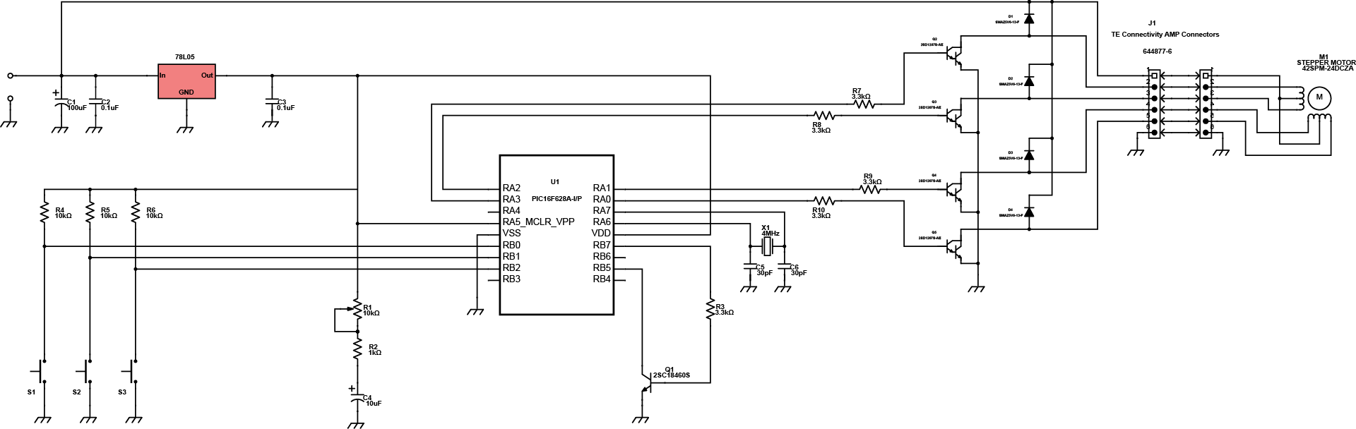
This project is designed particularly for industrial application, which features a typical stepper motor control. It enables the user to optimize application requirements since it is programmable. The main controller is equipped with NanoWatt technology in which it has power-saving sleep mode allowing the system to reduce its power consumption. It also makes use of MTA-100 connector enabling the system with feed-through capability for daisy-chain connection with insulation displacement contacts eliminating the need of strip wires.
In Detail
The circuit is comprised of a stepper motor connected to a controlling unit through MTA-100 connector. The MTA-100 connector is a TE connectivity connector that provides the terminating pins of the board to the motor. The Darlington transistors drive the permanent magnet of the motor while being protected against reverse voltages by a diode. The PIC16F628A-I/P serves as the main controller in which the input/output data are being processed. A variable resistor is provided for external supply adjustments. The pushbuttons are used to control the direction of the motor. The 78L05 is an LDO that ensures the supply of the system and operates with capacitor filters.
This design is suitable to several applications. It is used for controlling actuators and valves in manufacturing industries. It can be modified for applications that are not related to industrial and can still function as desired.
REMOTE, Appliance
REMOTE, Appliance
REMOTE, Appliance
REMOTE, Appliance
REMOTE, Appliance
In Brief
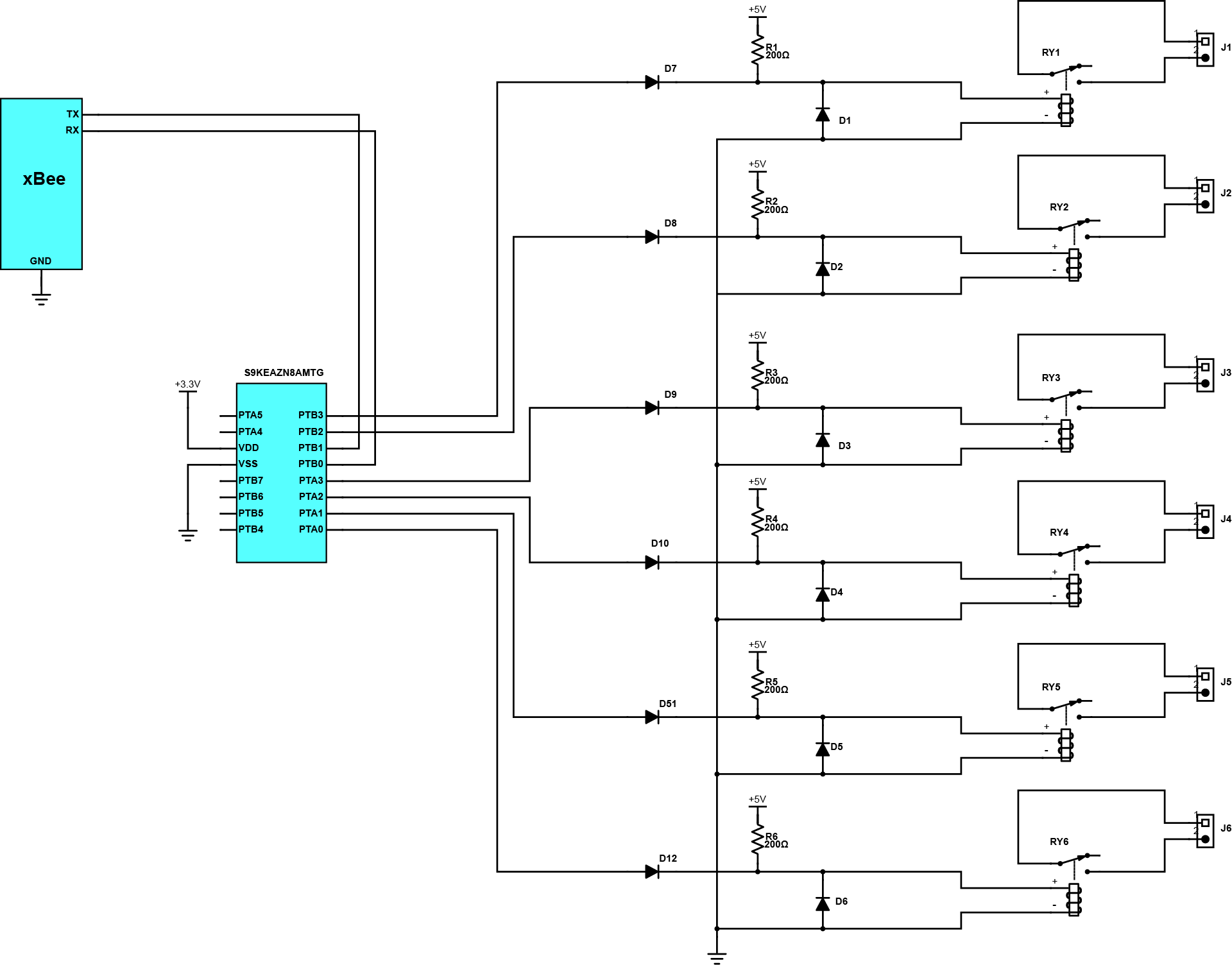
The control of electronic appliances using wireless module before requires critical analysis. Making this as easy as possible innovates people to provide new ideas. The design is a straightforward circuit that contributes to the development of home automation, which is the remote control manipulation of electronic devices. The system is controlled by a 32-bit ARM Cortex MCU that supports up to two SPI modules, three UART modules, two IIC modules, and one CAN module. It is energy efficient and durable even for industrial applications that requires the highest level of quality and longevity support.
In Detail
It is comprised of S9KEAZN8AMTG Freescale Kinetis E 32-bit MCU that controls the triggering of the reed relays, and the transmission and reception of signals through the xBee RF module. The triggering signals are with pull-ups to ensure the switching of relays will take place. The general purpose diodes in series are for the protection of the MCU pins while the diodes in parallel are protection for blowback voltage.
This design is applicable to different electronic appliances and some of the industrial instrumentation devices. It offers convenience to remote control interfacing between electronic devices and it can still be modified to optimise its applications.
SENSOR, Temperature Controlled Fan
SENSOR, Temperature Controlled Fan
SENSOR, Temperature Controlled Fan
SENSOR, Temperature Controlled Fan
SENSOR, Temperature Controlled Fan
In Brief
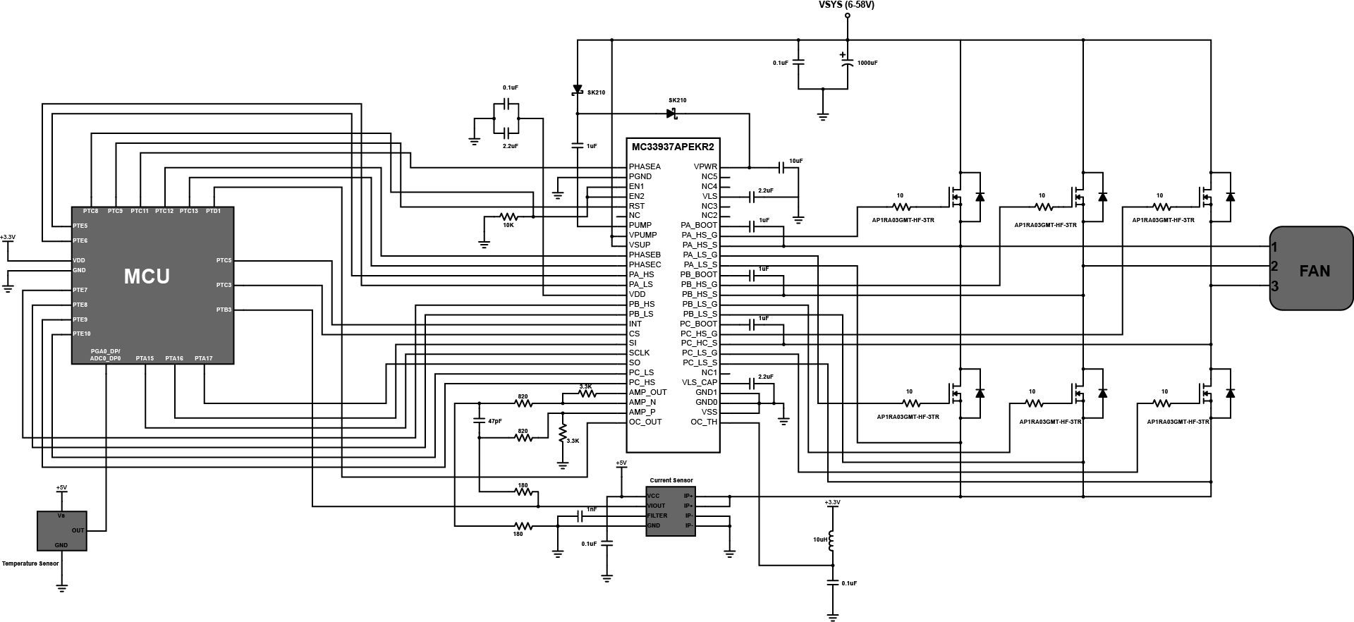
The excessive heat in an environment or in any system can cause problems or damages to the devices within that system. One way of solving that problem is to use a cooling fan to cool down the system. In this way we can guarantee that all devices will perform within its operating temperature range. However, another problem may appear because later on you will notice that even at lower temperature, the fan will still operate at its full speed and it is a waste of energy. This circuit solves that problem by adjusting automatically the speed of the cooling fan with respect to the system’s temperature.
In Detail
The circuit operation starts at sensing the temperature level of the system by using a temperature sensor. The output of the temperature sensor will be processed by the MCU’s analog-to-digital converter. After processing the data, the MCU will now control the pre-driver of the MOSFETs that drive the cooling fan with respect to the temperature. The pre-driver used in this circuit is the MC33937APEKR2. It is a field effect transistor pre-driver designed to drive three-phase motors. The MC33937 offers precise control and protection of DC motors with up to three phases. That is why it’s ideal to control cooling fan.
The power MOSFET used in this circuit is the AP1RA03GMT-HF-3TR N-channel Enhancement-mode type. These power MOSFETs drive the cooling fan with respect to current it receives from the pre-driver MC33937. This MOSFET can provide enough current to drive motors requiring much higher current than low speed motors. With this circuit, we can be able to regulate a system’s temperature and at the same time be able to conserve energy wasted by a constant speed cooling fan.
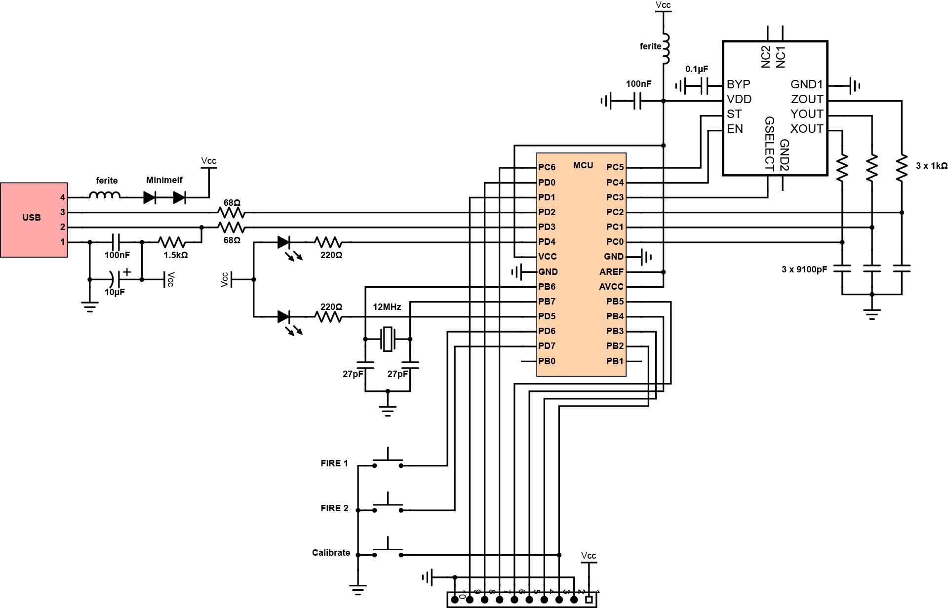
SENSOR, Tilt USB
SENSOR, Tilt USB
SENSOR, Tilt USB
SENSOR, Tilt USB
SENSOR, Tilt USB
In Brief
This USB tilt module is an acceleration sensing device. It is a two axis accelerometer to measure acceleration caused by motion or tilt. This device is also a USB dongle that allows it to connect to any device with USB interface like desktop computers and cellphones that support “on the go” USB connection.
In Detail
The self calibration mode has been added to allow for easy calibration without a special software tool running on the host; Press and hold the calibration button on the device for at least three seconds until the green LED turns off. The yellow calibration LED will then start blinking once a second to indicate that step one of the “self calibration” is in progress. Hold the device “flat” and press the calibration button again within 15 seconds. The yellow LED will start flashing twice each second to indicate that this was successful and that the second step of the calibration is to be performed. Tilt the device 90 degrees to the right and again press the calibration button within 15 seconds. The LED will start blinking three times each second. Tilt the device 90 degrees down and once more press the calibration button within 15 seconds. The LED will start blinking four times each second. Press the calibration button one last time within 15 seconds to permanently store the new calibration data inside the sticks internal EEPROM memory. The yellow LED will stop flashing and the green LED will turn on again. Calibration is done!
The accelerometers used on the device need to be calibrated in order to get accurate measurements in the range of -2G to +2G and to adjust the layout of the two axes to e.g. cope with the fact that the device may be oriented differently when attached to different host computers. The device can be used in conjunction with any software that can be controlled using a simple two axis joystick with two fire buttons, however, the device is not a joystick.